Single-wheel self-balancing electric vehicle capable of realizing wireless communication
A self-balancing electric vehicle, wireless communication technology, applied in vehicle components, rider drive, transportation and packaging, etc., can solve the problems of complex technology, hidden dangers, delay in traffic jams, etc., and achieve improved safety performance and simple device structure. , easy to carry effect
- Summary
- Abstract
- Description
- Claims
- Application Information
AI Technical Summary
Problems solved by technology
Method used
Image

Examples
Embodiment 1
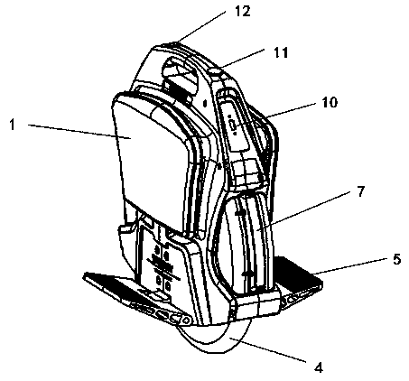
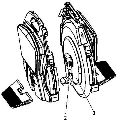
[0026] see figure 1 — Figure 4 , a wireless communication single-wheel self-balancing electric vehicle, said single-wheel self-balancing electric vehicle includes a housing 1, a column 2, a hub motor 3, a tire 4, a pedal 5, a circuit system 6, a light bar 7, and a battery pack 8. Auxiliary wheel 9, USB interface 10, indicator light 11, switch 12, charger 13 and client 14, the wheel of the electric vehicle is located at the center of the vehicle; the circuit system detects the change of the center of gravity of the operator before and after The forward and reverse of the vehicle is controlled by the motor; the single-wheel self-balancing electric vehicle realizes the wireless communication with the client through the circuit system. Among them, the client is a device that can communicate with the electric vehicle wirelessly, so as to check the driving parameters of the vehicle in real time, and can also set the speed limit value of the vehicle.
Embodiment 2
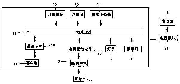
[0028] see image 3 , as an improvement of the present invention, the circuit system includes a microprocessor 18, a power module 21, an accelerometer 15, a gyroscope 16, a Hall sensor 17, a communication chip 19, and a motor drive circuit 20, and the microprocessor 18 is The core of the circuit system is used to collect information from the power module 21, accelerometer 15, gyroscope 16, Hall sensor 17, USB interface 10, and communication chip 19, and to monitor the motor, light bar 7, indicator light 11, and communication chip. 19 for control. The power module 21 is used to control the battery to supply power to the circuit board and the motor and to control the charging process of the battery; the gyroscope 16 and the accelerometer 15 are used to detect the inclination angle of the vehicle body; the Hall sensor 17 is located inside the motor to measure the driving speed of the vehicle ; The communication chip 19 is used to realize the wireless communication between the mi...
Embodiment 3
[0030] see image 3 , as an improvement of the present invention, the circuit system detects the change of the front and rear center of gravity of the operator and then controls the forward and backward of the vehicle through the motor; The inclination is detected, and the measured data is sent to the microprocessor 18. The microprocessor 18 calculates the rotational speed of the wheel according to the balance algorithm, and controls the rotation of the wheel through the motor drive circuit, thereby controlling the forward and backward of the vehicle. The rest of the structures and advantages are exactly the same as in Embodiment 1.
[0031]
PUM
 Abstract
Description
Claims
Application Information