Low-section-height drift-pillar-free shrinkage-stoping, subsequent-filling and mining method

A backfill mining method with no bottom pillar technology, which is applied in the direction of filling, ground mining, mining equipment, etc., can solve the problems of open pit expansion, large loss and dilution of back mining ore, large exposed area, etc., and achieve stope stability Good performance, high ore recovery rate, high degree of mechanization

Inactive Publication Date: 2014-02-05
WUHAN UNIV OF SCI & TECH
View PDF5 Cites 9 Cited by
  • Summary
  • Abstract
  • Description
  • Claims
  • Application Information

AI Technical Summary

Problems solved by technology

[0006] When the caving method is directly used to mine hanging side mines, it is easy to cause problems such as caving of surrounding rocks in gobs, collapse of roof rocks, surface subsidence, and expansion of open pits; When using the open field method with reserved pillars to mine hanging side mines, due to the long exposure time and large exposed area of ​​the rock in the mining area, the stability of the surrounding rock will decrease, which will affect the safety of the min

Method used


Image

  • Low-section-height drift-pillar-free shrinkage-stoping, subsequent-filling and mining method
  • Low-section-height drift-pillar-free shrinkage-stoping, subsequent-filling and mining method
  • Low-section-height drift-pillar-free shrinkage-stoping, subsequent-filling and mining method

Examples


Embodiment 1

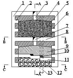
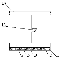
[0029] A low-section, high-pillar-free ore retention and subsequent filling mining method. The method described in this embodiment is:

[0030] 1) Sampling and cutting

[0031] This embodiment is the mining of a certain sporadic ore body. After the development project is completed, the sporadic ore body is divided into stages, such as figure 1 , figure 2 , image 3 and Figure 4 As shown, stage transportation lanes 14 are arranged at each stage, and the vein-piercing roadway 7 is excavated from the stage transportation lanes 14 to reach the mine room to be mined; in the spacer column 6, a connecting road 2 is arranged vertically to connect The distance between road 2 is 3.0~3.5m, and the ventilated pedestrian patio 1 is connected with the mine house through the connecting road 2; the cutting is carried out in the mine house after the mining is completed, and the height of the bottom formed by cutting is 2~2.5m. The bottom width is the thickness of the ore body.

[0032]...

Embodiment 2

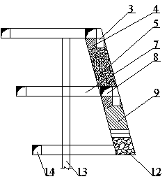
[0036] A low-section, high-pillar-free ore retention and subsequent filling mining method. The method described in this embodiment is:

[0037] 1) Sampling and cutting

[0038] This embodiment is the mining of a certain hanging side ore body. After the development project is completed, the hanging side ore body is divided into stages, such as Figure 5 , Figure 6 and Figure 7 As shown, stage transportation lanes 14 are arranged at each stage, and the vein-piercing roadway 7 is excavated from the stage transportation lanes 14 to reach the mine room to be mined; in the spacer column 6, a connecting road 2 is arranged vertically to connect The distance between road 2 is 3.5~4.0m, and the ventilated pedestrian patio 1 is connected with the mine house through the connecting road 2; the cutting is carried out in the mine house after the mining has been completed, the height of the bottom formed by cutting is 2~2.5m, and the The bottom width is the thickness of the ore body.

...


PUM

PropertyMeasurementUnit
Heightaaaaaaaaaa
Thicknessaaaaaaaaaa

Abstract

The invention relates to a low-section-height drift-pillar-free shrinkage-stoping, subsequent-filling and mining method. According to a technical scheme, a transverse-drift roadway (7) is tunneled in a stage main haulage roadway (14) arranged at each stage to access a chamber to be stoped. A cross gateway (2) is arranged in a stud (6), and a ventilation way shaft (1) is communicated with the chamber by the cross gateway (2). Bottom-pulling height formed by cutting is 2 m-2.5 m and the width is equal to the thickness of an ore body. Stoping in the chamber is carried out from bottom to top, and layering height is 2m-3m. Length of a bench working surface is 2m-4m, height is 1.5m-2m, blast holes (10) are horizontally formed, and arranged in a triangular manner, and space between the adjacent blast holes (10) is 0.8m-1m; 30%-40% volume of ores are discharged after blasting and ore dropping each time, and all ores are discharged after stoping of the chamber is completed. An air return roadway built at the bottom of a mined-out area is distributed along the vein direction, and then the mined-out area is filled. The method has the advantages of being high in stope stability, high in ore recovery rate and high in mechanical degree.

Description

technical field [0001] The invention belongs to the field of underground mining of ore deposits, and in particular relates to a low-section high-pillar-free ore retention and subsequent filling mining method. Background technique [0002] In underground mining, there are often a few sporadic cystic and nest-shaped small ore bodies far away from the main ore body. From the perspective of technology and economy, traditional mining methods are not suitable for mining this part of ore. In order to consider the overall benefit, many mines These ores are all abandoned, resulting in a great waste of resources. In addition, in the process of delineating the mining boundary in open-pit mining, due to the complex occurrence conditions of the ore deposit and the large changes in the shape of the ore body, some ore bodies are often not within the mining boundary, and this part of the ore remains on the side of the open pit, that is, the hanging side mine. According to data, after the ...

Claims


Application Information

Patent Timeline
IPC IPC(8): E21C41/16E21C47/00E21F15/00F42D3/04
Inventor 刘艳章张群张丙涛叶义成柯丽华王其飞邓磊赵卫石志军刘洋
Owner WUHAN UNIV OF SCI & TECH
Why Eureka
Try Eureka