
Unimpeded double-controlled vertical wind turbine

A technology for wind turbines and generators, which is applied to wind turbines, wind turbine combinations, and wind turbines at right angles to the wind direction, etc., can solve the problem of reducing service life, low wind energy utilization rate of wind turbines, and large voltage and current fluctuations. And other issues

Inactive Publication Date: 2014-02-05
仇立德
View PDF9 Cites 2 Cited by
  • Summary
  • Abstract
  • Description
  • Claims
  • Application Information

AI Technical Summary

Problems solved by technology

[0005]2. With the increase of the power of the wind turbine, the diameter of the wind blades is getting longer and longer, and the tip line speed of some wind blades has reached supersonic speed. Once a destructive storm comes, its wind blades will not be shortened, and it cannot protect itself. It can only rotate the angle of the wind blades to reduce some damage, but it cannot fundamentally solve the problem of wind protection. Once a "speeding car" occurs , the generator may be burned, and the electrical equipment directly coupled to it will be damaged to varying degrees
[0006]3. At present, the utilization rate of wind energy of wind turbines is extremely low, the maximum effective utilization rate of theoretical calculation is 42.5%, and the actual rate is only about 30%. Wind turbines can reach 70%, and large-scale hydroelectric generators can reach more than 85%. Compared with the utilization rate of hydroelectric generators, the utilization rate of wind turbine generators has a lot of room for improvement.
[0007]4. The lack of directness and rigidity in speed adjustment has a huge mechanical impact on the wind turbine. Frequent replacement of brake pads increases the number of maintenance and reduces the service life. Due to sudden changes in the generator speed, the output voltage and current fluctuate greatly, which reduces the quality of power transmission

Method used


Image

  • Unimpeded double-controlled vertical wind turbine
  • Unimpeded double-controlled vertical wind turbine
  • Unimpeded double-controlled vertical wind turbine

Examples


Embodiment Construction

[0014] The following is a detailed description of the unimpeded dual-control vertical wind turbine workflow:

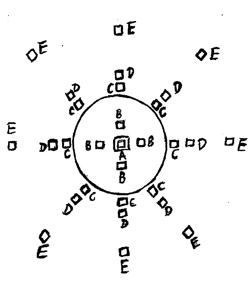
[0015] 1. Adjust the wind vane according to the direction of the wind at this moment ( Figure 4E in Z), so that the direction of the wind and the wind vane ( Figure 4E The direction indicated by Z) in is consistent.

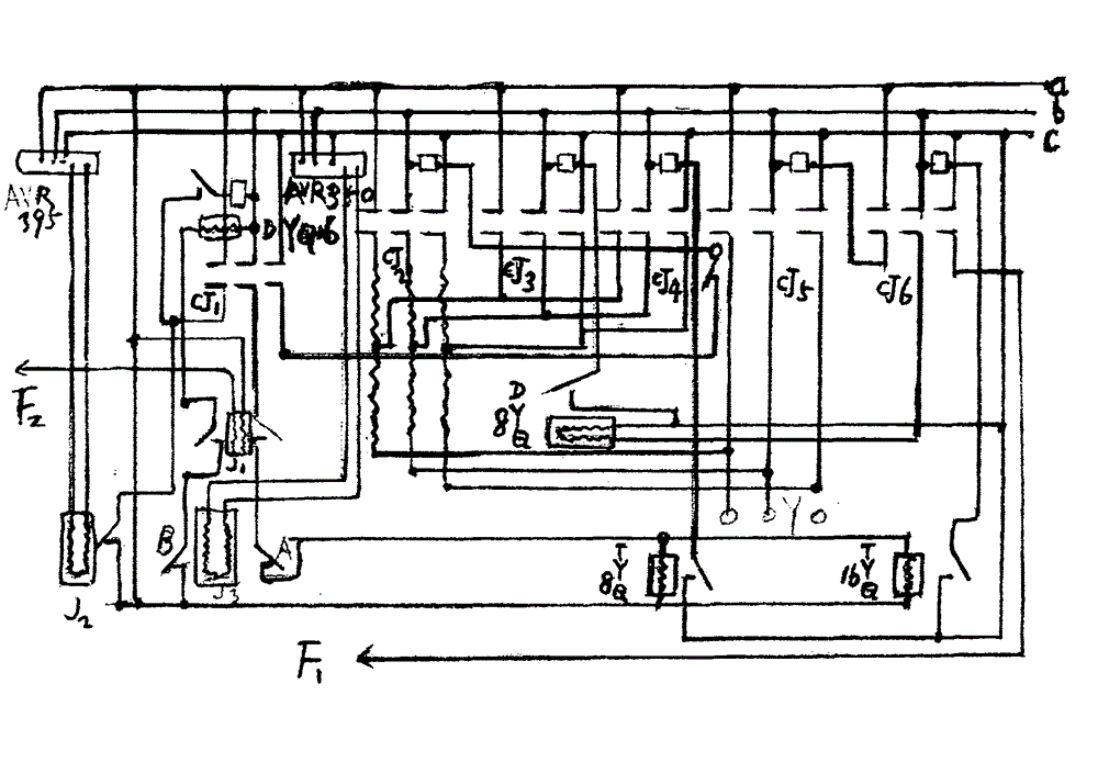
[0016] 2. Figure 7 Among them, ABC is the electric power supply, and abc is the wind power supply, according to the direction of the wind and the annular retaining wall ( Figure 4C The different positions of AF in ) are determined by the wind vane ( Figure 4E Z) in the command is issued through FA and FB. If there is an instruction from FA, the power-off delayer (DYQ) I is turned on, making its normally open contact turn from an open state to a closed state, the contactor CJ2 is closed, and the four vehicles ( Figure 4C AE in ) driven by the 3D motor, the annular retaining wall ( Figure 4C AF in the center) rotates slowly, when turned close ...


PUM


Abstract

Disclosed is an unimpeded double-controlled vertical wind turbine. A generator (G in a manual attached figure 4B) is disposed in wind blade boxes (AJ and AK in the manual attached figure 4B, and AL in the manual attached figure 4E), and maintenance and repairing of a central shaft (V in the manual figure 4B), a bottom-shaft assembly (V in the manual figure 4B) and the bottom of a circular concrete platform (T the in manual figure 4B) are needless of aerial professional staff. The generator (G in the manual attached figure 4B) is started up in two steps one after the other under the action of a clutch, and start-up wind speed and rated power wind speed are enabled to tend to be identical. A circular retaining wall (AF in a manual attached figure 4C) is arranged for air regulation, so that the purpose of rated rotating speed and power is achieved, and a speed limiting device of an existing brake block is omitted.

Description

[0001] [0001] 1. Technical field of unimpeded dual-control vertical wind turbine [0002] Technical field of unimpeded dual-control vertical wind power generator: it belongs to the category of new energy, and has strong practicability, significant economic benefits, great development value, and great future prospects. The arid and vast desert, the economically developed coast, and the remote frontier coastal defense posts all provide a broad space for the development of wind turbines. 2. Background technology [0003] Background technology: With the continuous increase of MW level in today's wind power generators, problems to be solved continue to emerge: [0004] 1. The first problem to be solved is the lightning attack. The tall power generation tower has erected the generator in the clouds. The generator works in the environment of lightning, thunder, wind and rain, which is very easy to cause lightning attack. Despite the efforts of many scientific workers, the develop...

Claims


Application Information

Patent Timeline
IPC IPC(8): F03D3/00F03D7/06F03D9/00
CPCY02E10/74
Inventor 仇立德
Owner 仇立德
Learn More