Optical exposure equipment, exposure method adopted by optical exposure equipment and display device production system

A technology of optical alignment and alignment, applied in optics, nonlinear optics, instruments, etc., can solve the problems of high light intensity, high manufacturing cost, and poor flexibility in adjusting illumination uniformity, so as to achieve uniform optical alignment, ensure quality, and avoid optical alignment The effect of poor uniformity

Active Publication Date: 2014-02-05
BOE TECH GRP CO LTD +1
View PDF4 Cites 13 Cited by
  • Summary
  • Abstract
  • Description
  • Claims
  • Application Information

AI Technical Summary

Problems solved by technology

Due to the limitation of the manufacturing process of the long lamp tube 11, it is difficult to control the illumination uniformity of the long lamp tube 11 in the effective light-emitting area, and the longer the lamp tube, the worse the illumination uniformity, and the adjustment flexibility of the illumination uniformity It is also poor, which has great limitations in the application of photo-alignment technology for large-generation LCD panels
Simultaneously, because the long high-pressure mercury lamp tube 11 is made of quartz material, the lamp tube of this material is fragile, and the longer the lamp tube length, the higher the manufacturing cost and the more expensive the price, which will inevitably increase the production cost.
In addition, with the development of photosensitive alignment film materials, low-illuminance materials are increasingly becoming a development trend. When forming alignment films, they require low exposure energy, short alignment process time, and large production capacity. They have advantages in actual production. However, the light intensity of the long lamp tube 11 is generally high, and when the required exposure energy is low, the long lamp tube 11 is often unable to cope with

Method used


Image

  • Optical exposure equipment, exposure method adopted by optical exposure equipment and display device production system
  • Optical exposure equipment, exposure method adopted by optical exposure equipment and display device production system
  • Optical exposure equipment, exposure method adopted by optical exposure equipment and display device production system

Examples


Embodiment 1

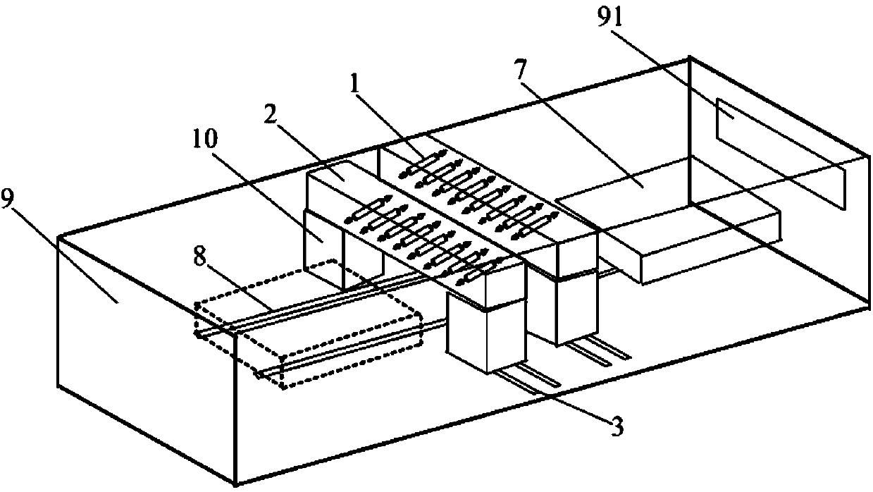
[0040] This embodiment provides an optical alignment device, which includes an optical alignment mechanism and an alignment area for a substrate to be aligned. The optical alignment mechanism includes an alignment unit and a stepping unit for driving the alignment unit to move. The alignment unit is used to align the substrate to be aligned. The unit includes a plurality of light sources arranged uniformly at intervals, and the stepping unit is used to drive the alignment unit to move, and the movement direction of the alignment unit is the same as the arrangement direction of the light sources.

[0041] Below to figure 2 As an example, the solution of the present invention is introduced in detail.

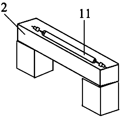
[0042] Such as figure 2 As shown, the light source can include a line light source 1, and the alignment unit also includes a box body 2, the box body 2 can be in the shape of a cuboid (of course, it can also be in other shapes), and a plurality of line light sources 1 are arran...

Embodiment 2

[0069] This embodiment provides an optical alignment device. The difference from Embodiment 1 is that N=1 in this embodiment, that is, the alignment unit includes only one box 2 . Other structures and settings of the optical alignment device are the same as those in Embodiment 1, and will not be repeated here.

[0070] This embodiment also provides an alignment method of the optical alignment device, which is different from the alignment method in Embodiment 1 in that it is based on the illumination intensity of the line light source 1 selected in Embodiment 1 and the set adjacent line light source 1 (that is, the number of line light sources 1 in a box 2 is also the same as that in Embodiment 1), and on the basis that the stepping unit drives the alignment unit to move a stepping distance L / 4 at a time, The alignment unit in this embodiment needs to step and move in the same direction three times. Correspondingly, the substrate to be aligned needs to go back and forth along t...

Embodiment 3

[0076] This embodiment provides an optical alignment device. The difference from Embodiment 1-2 is that in this embodiment, N=3, that is, the alignment unit includes three identical boxes, and the adjacent boxes are sequentially staggered in the length direction by L The / 3 spacing is arranged, so that the spacing between two adjacent line light sources in any two adjacent boxes of the three boxes is L / 3. The moving distance of the alignment unit along the first track driven by the stepping unit once is L / 6. Other structures and settings of the optical alignment device are the same as those in Embodiment 1, and will not be repeated here.

[0077] In this embodiment, since the spacing L between adjacent line light sources in a single box is the same as that in Embodiment 1, the spacing between two adjacent line light sources in two adjacent boxes is set to L / 3, And the single movement distance of the alignment unit is set to L / 6, so that the alignment unit can more uniformly i...


PUM

PropertyMeasurementUnit
wavelengthaaaaaaaaaa

Abstract

The invention provides optical exposure equipment, an exposure method adopted by the optical exposure equipment and a display device production system. The optical exposure equipment comprises an optical exposure mechanism and an exposure region for a substrate to be oriented; the optical exposure mechanism comprises an exposure unit and a stepping unit for driving the exposure unit to move; the exposure unit is used for carrying out exposure on the substrate to be oriented; the exposure unit comprises a plurality of light sources which are uniformly arranged at intervals; the stepping unit is used for driving the exposure unit to move; the movement direction of the exposure unit is the same as the arrangement direction of the light sources. According to the optical exposure equipment, by the arrangement of the stepping unit, the exposure unit can move to an illumination intensity relatively-weak region along with the stepping unit and meanwhile, the exposure unit can still have uniform illumination intensity after moving, so that the exposure unit is more uniform in carrying out optical exposure in the whole exposure process to further avoid causing defectiveness of an orientation film on the surface of the substrate to be oriented due to poor optical exposure uniformity, and thus, the quality of a display panel adopting the oriented substrate is further ensured.

Description

technical field [0001] The present invention relates to the field of display technology, in particular to an optical alignment device, an alignment method thereof, and a display device production system. Background technique [0002] A liquid crystal display panel is usually formed by combining an upper substrate and a lower substrate, and liquid crystals are filled in the gap formed by combining the upper substrate and the lower substrate. Wherein: the upper substrate includes an upper glass substrate, a polarizing plate and three primary color filters for realizing colorization of images. The lower substrate includes a lower glass substrate, a conductive glass microplate, semiconductor switching devices and vertical and horizontal lines connecting the semiconductor switching devices, and is used to control the deflection of liquid crystal molecules. In order to ensure the alignment direction of the liquid crystal molecules in the initial state, an alignment film is usuall...

Claims


Application Information

Patent Timeline
Patent Type & Authority Applications(China)
IPC IPC(8): G02F1/1337
Inventor 张猛韩海滨屠桂朋王源源
Owner BOE TECH GRP CO LTD
Why Eureka
Try Eureka