
Anti-wind self-adaptive compensation method for large antenna

An adaptive compensation and antenna technology, applied in adaptive control, instruments, control/regulation systems, etc., can solve problems such as low efficiency, limited effect, and no consideration of flexible vibration

Inactive Publication Date: 2014-02-05
XIDIAN UNIV
View PDF1 Cites 18 Cited by
  • Summary
  • Abstract
  • Description
  • Claims
  • Application Information

AI Technical Summary

Problems solved by technology

[0009] However, for controlling the pointing error caused by wind disturbance, the existing methods are either based on considering the rigid rotation angle as the pointing output, without considering the control of flexible vibration, which greatly reduces the accuracy of error compensation; Wind direction, under different reflector angles, testing a large number of pointing error data to build a table, the workload is heavy, the efficiency is low, and the compensation given is only the average value, although the pointing error can be reduced to a certain extent, the effect is limited

Method used


Image

  • Anti-wind self-adaptive compensation method for large antenna
  • Anti-wind self-adaptive compensation method for large antenna
  • Anti-wind self-adaptive compensation method for large antenna

Examples


Embodiment Construction

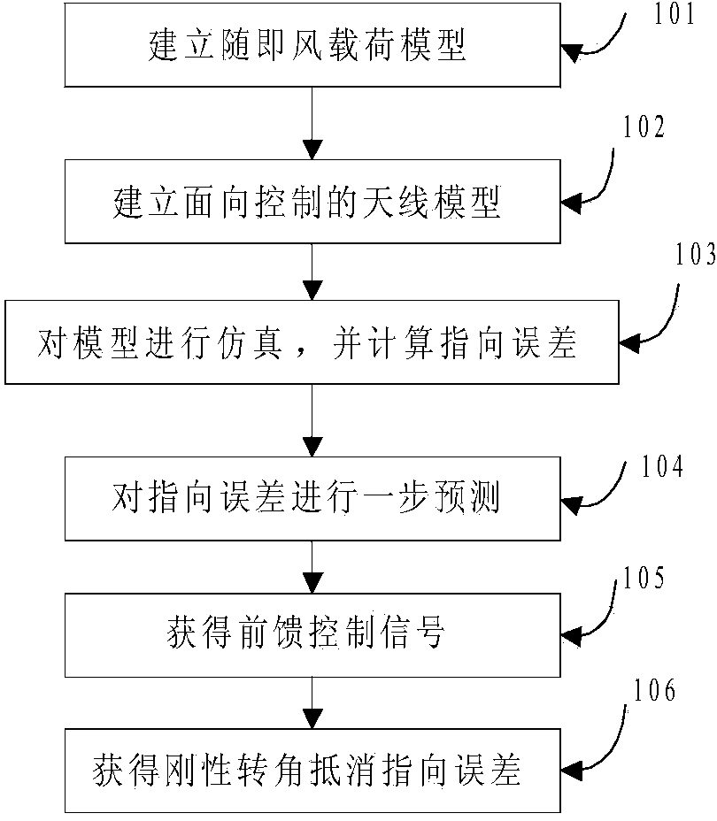
[0136] Such as figure 1 As shown, a large-scale antenna anti-wind disturbance adaptive compensation method is characterized in that it includes at least the following steps:

[0137] Step 101: establishing a relatively accurate random wind load model at the antenna position;

[0138] Step 102: Establish a control-oriented model containing antenna flexibility information;

[0139] Step 103: By simulating the built wind model and antenna model, the flexible oscillation information of the antenna is obtained, and the pointing error is calculated;

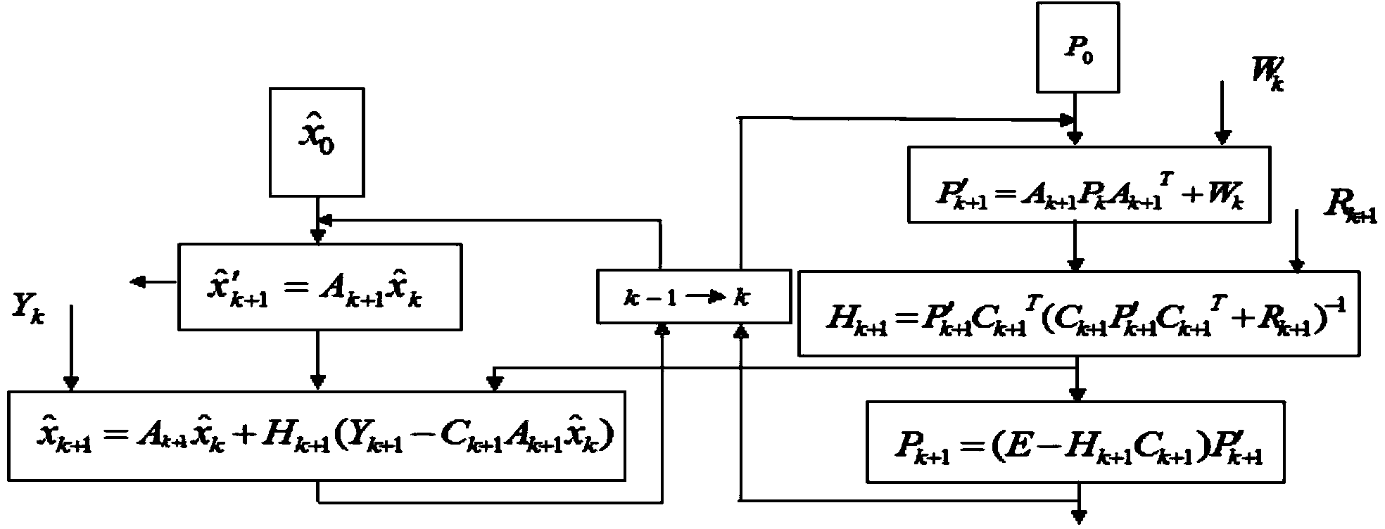
[0140] Step 104: Predict the pointing error in one step according to the Kalman filter method, and the prediction time is the sum of the inertial time constant of the motor and the inertial time constant of the filter;

[0141] Step 105: designing a low-pass filter, obtaining the transfer function of the antenna model and the motor reducer model, performing reverse calculation on the predicted value, and obtaining the feedforward con...


PUM


Abstract

The invention relates to an anti-wind self-adaptive compensation method for a large antenna. The anti-wind self-adaptive compensation method for the large antenna is characterized by at least including the first step of establishing an accurate random wind load model at the position of the antenna, the second step of establishing a control-oriented model containing flexible information of the antenna, the third step of carrying out simulation on the established wind model and an antenna model, obtaining the flexible oscillation information of the antenna and calculating pointing errors, the fourth step of further predicting the pointing errors according to the Kalman filtering mode, wherein the prediction time equals the sum of an inertia time constant of a motor and an inertia time constant of a filter, the fifth step of designing a low-pass filter, solving a transfer function of the antenna model and a motor reducer model, and carrying out backstepping calculation on a predicted value to obtain a feedforward control signal, and the sixth step of feeding forward feedforward control voltage to a control system so as to enable the controlled model to produce a rigid rotation angle to offset the pointing errors caused by flexible oscillation. Through the method, pointing accuracy, electrical performance and work efficiency of the antenna are improved.

Description

technical field [0001] The invention relates to the technical field of antennas, in particular to an adaptive compensation method for anti-wind disturbance of a large antenna. Background technique [0002] Large-scale reflector antennas are widely used in satellite communications, deep space exploration and other fields due to their advantages of high irradiation efficiency and low edge leakage. However, the design indicators of large-scale reflector antenna pointing controllers are relatively high. For a 65-meter aperture antenna, the pointing accuracy requires an error of less than 0.01°. Only when the pointing accuracy meets the requirements can the efficiency of the antenna aperture be brought into play. As the antenna aperture continues to increase, the problem of pointing inaccuracy caused by gust disturbances will become less It becomes more and more serious, and the pointing deviation will lead to the deterioration of the electrical performance of the antenna, which ...

Claims


Application Information

Patent Timeline
Patent Type & Authority Applications(China)
IPC IPC(8): G05B13/04G05D3/12
Inventor 黄进张洁范建宇宋瑞雪邱丽丽
Owner XIDIAN UNIV
Learn More