Tool path forming method based on curved surface morphology and curved surface dynamics of machined workpiece

A tool path and workpiece processing technology, which is applied in the field of computer-aided manufacturing, can solve problems affecting the performance of workpieces, and achieve the effects of improving service life, avoiding damage, and preventing cracks

Inactive Publication Date: 2014-02-05
UNIV OF JINAN
View PDF6 Cites 6 Cited by
  • Summary
  • Abstract
  • Description
  • Claims
  • Application Information

AI Technical Summary

Problems solved by technology

[0004] In view of the above deficiencies, the present invention provides a tool path formation method based on the surface morphology and surface dyn

Method used


Image

  • Tool path forming method based on curved surface morphology and curved surface dynamics of machined workpiece
  • Tool path forming method based on curved surface morphology and curved surface dynamics of machined workpiece
  • Tool path forming method based on curved surface morphology and curved surface dynamics of machined workpiece

Examples


Embodiment Construction

[0022] Embodiments of the present invention will be further described in detail below in conjunction with the accompanying drawings.

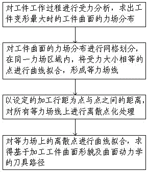
[0023] like figure 1 As shown, a kind of tool path formation method based on machining workpiece curved surface topography and curved surface dynamics of the present invention, it comprises the following steps:

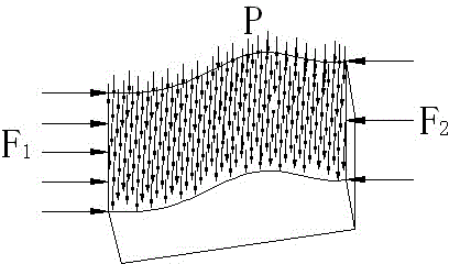
[0024] Step 1: If figure 2 As shown, taking the workpiece surface shape as the entry point, the force analysis of the workpiece working process is carried out, the workpiece solid model is established in the ANSYS software, and the six degrees of freedom of the lower surface of the workpiece are constrained, and the solid element Brick 8nbode 45 is selected for the workpiece solid model. Carry out mesh division, apply distributed force P on the upper surface of the solid model, apply uniform force F1 on the left surface of the solid model, and apply uniform force F2 on the right surface of the solid model, and obtain the force field ...


PUM


Abstract

The invention provides a tool path forming method based on curved surface morphology and curved surface dynamics of a machined workpiece. The method includes the first step of carrying out force analysis on the working process of the workpiece to figure out the force field distribution of the curved surface of the workpiece when deformation of the workpiece is maximum, the second step of carrying out grid division on the force field distribution of the curved surface of the workpiece and carrying out curve fitting on points with the same applied force in the same force field region to form an equal force field line, the third step of carrying out discrete pointillized processing on all the equal force field lines with a set machining line spacing as the distance between the points, and the fourth step of carrying out curve fitting on discrete points in equal force fields to obtain a tool path based on the curved surface morphology and the curved surface dynamics of the machined workpiece. Through the method, the tool path is determined according to force analysis conditions so as to enable the direction of the tool path to be parallel to the forced direction of the curved surface, and consequently the phenomenon that the curved surface of the workpiece cracks due to tooling is prevented to the maximum extent. Furthermore, the damage of plunge milling tool marks to the textiles of the curved surface of the workpiece is prevented, and the service life of the workpiece is prolonged.

Description

technical field [0001] The invention relates to a method for forming a tool path based on the shape and dynamics of the curved surface of a processed workpiece, and belongs to the technical field of computer aided manufacturing (computer Aided Manufacturing, CAM). Background technique [0002] Complex surface components are widely used in transportation, energy and defense industries, and their manufacturing level represents the core competitiveness of the country's manufacturing industry. With the development of new technology for complex surface digital manufacturing, traditional geometric principles, models and algorithms have shown many disadvantages. In terms of tool path generation, the existing equal parameter method, equidistant section plane method and equal residual height method, etc. These methods are also the basic methods for generating five-axis tool paths in the current five-axis simultaneous machining of complex surfaces. The calculation of the tool path ge...

Claims


Application Information

Patent Timeline
IPC IPC(8): G05B19/4097
Inventor 邓永红曹树坤李栋孔强蒋楠李世建白杨田娜
Owner UNIV OF JINAN
Why Eureka
Try Eureka