Device capable of simultaneously conducting power supplying and charging on mobile electronic device

A technology for mobile electronic equipment and charging devices, which is applied to battery circuit devices, circuit devices, current collectors, etc., can solve the problems of simultaneous power supply and low power supply efficiency of charging power, so as to improve power supply efficiency, improve design flexibility, and reduce resistance Effect

Active Publication Date: 2014-02-05
WUXI ZGMICRO ELECTRONICS CO LTD
View PDF10 Cites 13 Cited by
  • Summary
  • Abstract
  • Description
  • Claims
  • Application Information

AI Technical Summary

Problems solved by technology

[0007] One of the objects of the present invention is to solve the problem of low power supply efficiency of the above-mentioned simultaneous power supply and charging power supply

Method used


Image

  • Device capable of simultaneously conducting power supplying and charging on mobile electronic device
  • Device capable of simultaneously conducting power supplying and charging on mobile electronic device
  • Device capable of simultaneously conducting power supplying and charging on mobile electronic device

Examples


no. 1 example

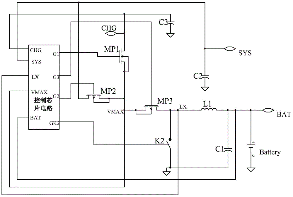
[0034] Such as figure 2 As shown, the present invention provides a device capable of supplying power and charging to mobile electronic devices at the same time, including: a control chip, a field effect transistor switch device at the device end, a field effect transistor at the battery end (hereinafter referred to as MP3), and a device for accessing mobile electronic devices. The mobile device terminal (hereinafter referred to as SYS), the adapted power supply terminal (hereinafter referred to as CHG) used to connect to the adapted power supply, the battery terminal used to connect to the battery (hereinafter referred to as BAT), the charging switch (hereinafter referred to as K2), Charging inductance (hereinafter referred to as L1), wherein, the adapted power supply terminal, mobile device terminal, and battery terminal are all grounded via filter capacitors, as shown in C1, C2, and C3 in the figure; the control chip includes an adapted power supply terminal input pin (for ...

no. 2 example

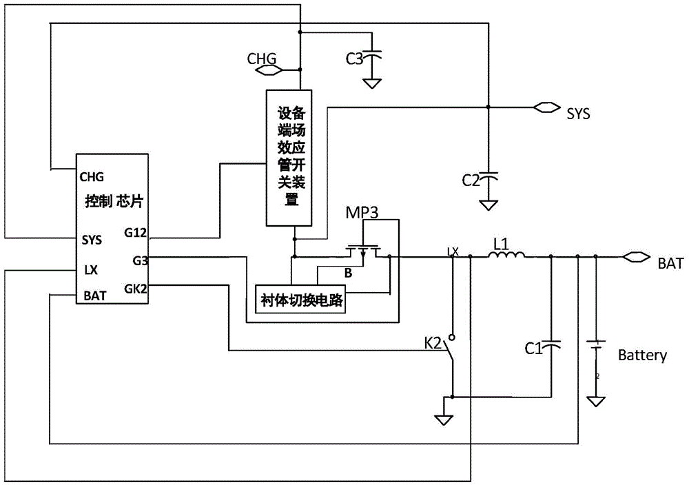
[0038] Such as image 3 As shown, the device end field effect transistor switching device includes a first field effect transistor (hereinafter referred to as MP1) and a second field effect transistor (hereinafter referred to as MP2) connected in series, and the drain of the first field effect transistor is connected to the The adapted power supply terminal, the source of the first field effect transistor is connected to the drain of the second field effect transistor, and the gates of the first field effect transistor and the second field effect transistor are connected to the device terminal switch control pin, the drain of the second field effect transistor is connected to the source of the battery terminal field effect transistor and the terminal of the mobile device, and the drain of the battery terminal field effect transistor is connected in series via the inductor to Battery terminals; the first field effect transistor, the second field effect transistor, and the batte...

no. 3 example

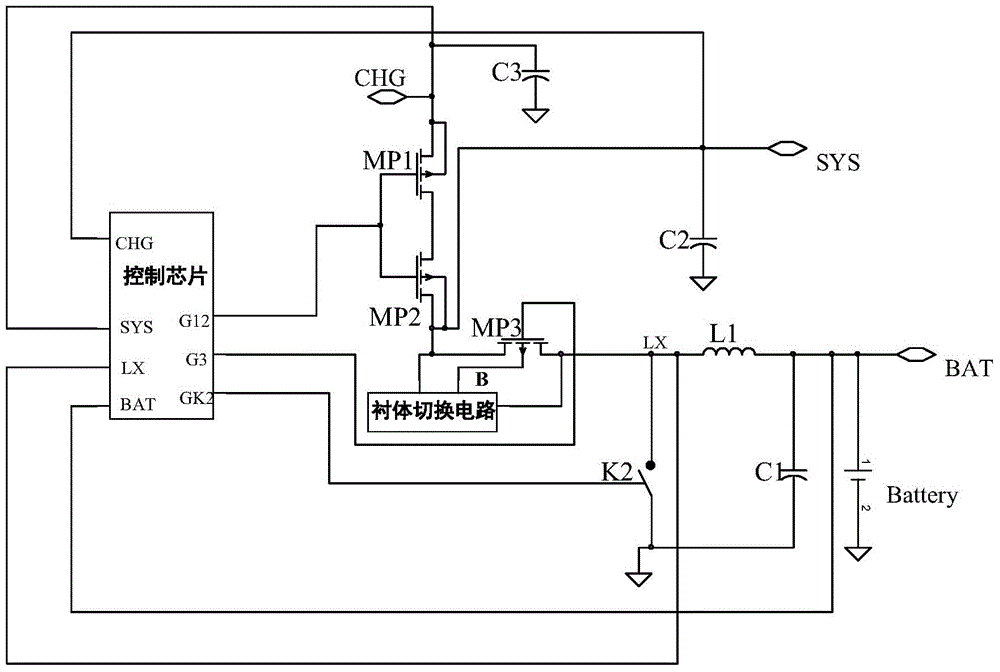
[0043] Figure 4 The third embodiment of the present invention is shown. Compared with the second embodiment, the main difference of this embodiment is that: the liner terminals of the first field effect transistor and the second field effect transistor are connected and connected to the The connection between the source of the first field effect transistor and the drain of the second field effect transistor, that is, the substrates of MP1 and MP2 are connected together, and the directions of the parasitic body diodes of the two are still opposite, so the function of bidirectional current prohibition can also be realized .

[0044] Compared with the second embodiment and the second embodiment, the second embodiment is a preferred solution. The reason is that when MP1 and MP2 are separated PMOS transistors, double PMOS transistors packaged in one package can be selected for use. For the trench gate technology (Trench Technology) that is usually used to manufacture power PMOS, ...


PUM


Abstract

The invention relates to a device capable of simultaneously conducting power supplying and charging on a mobile electronic device. The improvement is carried out on the basis of an existing power source capable of simultaneously conducting power supplying and charging, the connection mode of a field-effect tube serving as a switch is improved to enable resistance output by a battery to a mobile device power supply access to be reduced, a lining switching circuit for the field-effect tube is additionally arranged, electric leakage of a parasitic diode on the field-effect tube is effectively avoided, a control chip circuit is optimized to enable the device to be efficient, port resources are saved, the power supply efficiency is accordingly promoted, meanwhile, the design cost is reduced, and the design flexibility is promoted.

Description

Technical field: [0001] The invention relates to a power supply device, in particular to a power supply device for powering and charging mobile electronic equipment. Background technique: [0002] Mobile electronic devices are quite popular. Common devices include mobile phones, tablet computers, laptops, etc., all of which have batteries. Commonly used adaptive power supplies can not only directly supply power to the device but also charge the battery attached to the device when connected to the device. [0003] figure 1 Describes a prior art implementation of a mobile power supply that can simultaneously charge a device battery (hereinafter referred to as Battery) and supply power to a device system (hereinafter referred to as SYS). Among them, the control chip circuit is implemented by an integrated circuit, and a plurality of field effect transistors (hereinafter referred to as MP1, MP2, MP3) and switch tubes (hereinafter referred to as K2) that play a switch role are i...

Claims


Application Information

Patent Timeline
Patent Type & Authority Applications(China)
IPC IPC(8): H02J7/00
Inventor 王钊尹航田文博
Owner WUXI ZGMICRO ELECTRONICS CO LTD
Why Eureka
Try Eureka