DC-DC conversion circuit and DC-DC chip

A DC-DC, conversion circuit technology, applied in the field of DC power conversion, can solve problems such as high cost and complicated soft-start circuit design, and achieve the effects of simple design, suppression of surge current, and elimination of voltage overshoot

Inactive Publication Date: 2014-02-05
SHENZHEN SKYWORTH RGB ELECTRONICS CO LTD
View PDF6 Cites 4 Cited by
  • Summary
  • Abstract
  • Description
  • Claims
  • Application Information

AI Technical Summary

Problems solved by technology

[0004] The present invention provides a DC-DC conversion circuit, aiming to solve the problems of complex soft-start circuit design and high cost in the existing DC-DC conversion circuit

Method used


Image

  • DC-DC conversion circuit and DC-DC chip
  • DC-DC conversion circuit and DC-DC chip
  • DC-DC conversion circuit and DC-DC chip

Examples


Embodiment 1

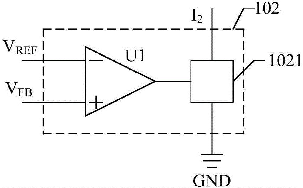
[0041] figure 2 The module structure of the shunt module 102 provided by the first embodiment of the present invention is shown. For the convenience of description, only the parts related to the first implementation of the present invention are listed, and the details are as follows:

[0042] Such as figure 2 As shown, as an embodiment of the present invention, the shunt module 102 includes a first operational amplifier U1 and a first switch tube 1021;

[0043]The inverting input end of the first operational amplifier U1 is the first power supply end of the shunt module 102, the non-inverting input end of the first operational amplifier U1 is the second power supply end of the shunt module 102, and the output end of the first operational amplifier U1 is connected to the second power supply end of the shunt module 102. The control end of a switch tube 1021 is connected, the high potential end of the first switch tube 1021 is the input end of the shunt module 102 , and the lo...

Embodiment 2

[0051] Figure 5 The module structure diagram of the shunt module provided by the second embodiment of the present invention is shown. For the convenience of description, only the parts related to the embodiment of the present invention are listed, and the details are as follows:

[0052] Such as Figure 5 As shown, as an embodiment of the present invention, the branching module 102 includes:

[0053] A first PMOS field effect transistor Q3, a second PMOS field effect transistor Q4, a third PMOS field effect transistor Q5, a fourth NMOS field effect transistor Q6, and a second switching transistor 1022;

[0054] The gate of the first PMOS field effect transistor Q3 is the first power supply terminal of the shunt module 102, the source of the first PMOS field effect transistor Q3 is connected to the drain of the second PMOS field effect transistor Q4, and the source of the third PMOS field effect transistor Q5 pole connection, the gate of the second PMOS field effect transist...


PUM


Abstract

The invention belongs to the field of direct current conversion, and provides a DC-DC conversion circuit and a DC-DC chip. The DC-DC conversion circuit and the DC-DC chip are characterized in that a current dividing module is controlled according to changes of the feedback voltage at the DC-DC output end to carry out current division on a charging current of a charging and discharging module, the charging current of the charging and discharging module is accordingly changed, then the charging time of a charging and discharging capacitor is changed, the oscillation period of an oscillation circuit is further changed, and the soft start aim is achieved. According to the DC-DC conversion circuit, the soft start period of the DC-DC conversion circuit can be adjusted, pins special for the chip are not required, the capacity of the charging and discharging capacitor is not required to be increased, the design is simple, the cost of the DC-DC conversion circuit is reduced, a surge current at the output end when the DC-DC conversion circuit is started can be suppressed, and voltage overshooting is avoided.

Description

technical field [0001] The invention belongs to the field of direct current conversion, and in particular relates to a DC-DC conversion circuit and a DC-DC chip. Background technique [0002] When the DC-DC conversion circuit is powered on, there will be a large surge current at the output end, and there may be voltage overshoot, which will cause uncertain effects on the electronic system where the DC-DC conversion circuit is located, so soft start is required To realize the smooth start of the DC-DC conversion circuit, to limit the inrush current and eliminate the overshoot of the output voltage. [0003] The general soft-start circuit requires a dedicated pin of the chip to connect an external capacitor to achieve the function of soft-start, which causes the complexity of the circuit and the increase of the application cost when the chip is applied. In the prior art, the DC-DC conversion circuit (chip) is integrated with a soft start circuit, but since the time of soft st...

Claims


Application Information

Patent Timeline
Patent Type & Authority Applications(China)
IPC IPC(8): H02M3/07H02M1/36
Inventor 王卫田
Owner SHENZHEN SKYWORTH RGB ELECTRONICS CO LTD
Why Eureka
Try Eureka