LED drive circuit structure with separated switching tube

A technology of LED driving and circuit structure, which is applied in the direction of electric lamp circuit layout, electric light source, lighting device, etc., can solve the problems of large voltage drop of MOS tube, competition, harmonic interference, etc., and achieves increased driving current, increased driving efficiency, and improved The effect of power factor

Active Publication Date: 2014-02-05
SHINEON BEIJING TECH
View PDF5 Cites 14 Cited by
  • Summary
  • Abstract
  • Description
  • Claims
  • Application Information

AI Technical Summary

Problems solved by technology

[0007] 1. The driving efficiency is not high
Due to the large voltage drop of the MOS tube at some operating points, the driving efficiency is difficult to reach more than 90%, which makes it difficult for this type of drive to compete with the switching power supply drive in terms of efficiency.
[0008] 2. The power factor is not high
[0009] 3. Harmonic interference
This problem is more prominent than point 2
[0010] 4. Mismatch with some TRIAC (three-terminal bidirectional AC switch) dimming equipment
Since the on and off of the TRIAC is controlled by the conduction current, when the conduction current is excessively fed back, the TRIAC will form a bistable state at some operating points. There will be flickering in the light, such flickering is unacceptable to customers in the application

Method used


Image

  • LED drive circuit structure with separated switching tube
  • LED drive circuit structure with separated switching tube
  • LED drive circuit structure with separated switching tube

Examples


Embodiment Construction

[0034] Hereinafter, the embodiments of the present invention will be described in detail with reference to the accompanying drawings. It should be noted that the embodiments in the application and the features in the embodiments can be combined with each other arbitrarily if there is no conflict.

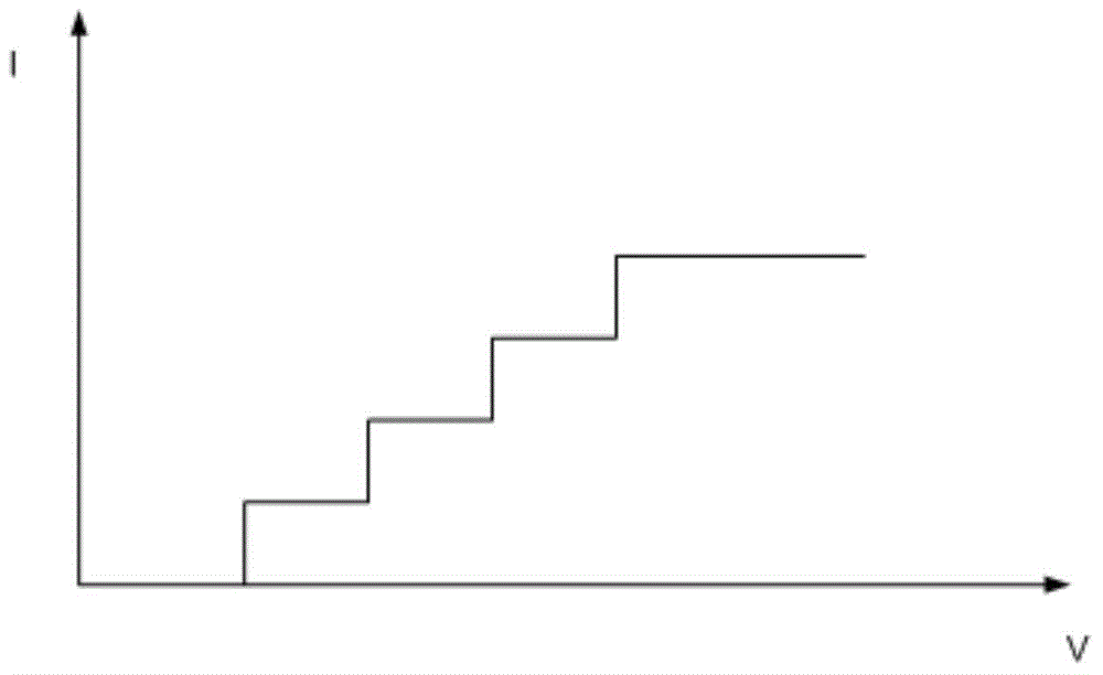
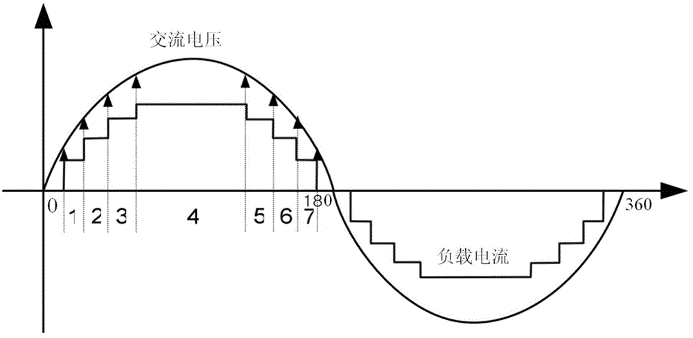
[0035] The present invention proposes a new current feedback control mechanism (Algorithm). The core idea is that when the input voltage changes within a certain lamp string conduction interval, the current is not a constant, but linearly changes with the voltage.

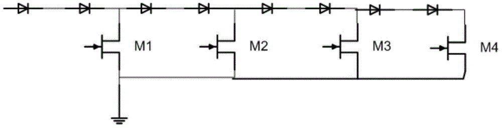
[0036] Such as Figure 4 As shown, the switch tube separated LED drive circuit structure includes a series topology structure, an input voltage detection unit, a load current detection unit, and a control unit. Among them, the series topology is similar to that described above figure 1 The structure includes one or more series drive modules, the series drive module includes a MOS tube and an LED string, and the MOS tube and t...


PUM


Abstract

The invention discloses an LED drive circuit structure with a separated switching tube. The LED drive circuit structure with the separated switching tube comprises a series connection topological structure, an input voltage detection unit, a load current detection unit and a control unit. The series connection topological structure comprises one or more series connection drive modules. The input voltage detection unit and the load current detection unit are respectively connected with the control unit. The input voltage detection unit is used for detecting the input voltage of the series connection topological structure, and outputting information of the input voltage to the control unit. The load current detection unit is used for detecting a load current of each series connection drive module, and outputting information of the load currents to the control unit. The control unit is connected with the grid electrode of an MOS tube in each series connection drive module, and is used for controlling the voltage of the grid electrode of each MOS tube according to the information of the input voltage and the information of the load currents, so that the load currents are in direct proportion to the input voltage when LED strands are conductive. By means of the LED drive circuit structure, drive efficiency is improved, a power factor of a circuit is improved, and the compatibility between the circuit and a TRIAC light modulator is improved.

Description

Technical field [0001] The present invention relates to the field of LED (light emitting diode) lighting, in particular to a switch tube separated LED drive circuit structure. Background technique [0002] LED chips are widely used in the field of new energy-saving light sources with their high efficiency, high integration, and long life. In the LED light source, power drive is a key technology. Due to the high integration and low cost requirements for LED applications, LED drive solutions without energy storage devices such as inductors and capacitors have taken up an increasing share of the market, and will become mainstream LED drive solutions in future applications. In this type of driving scheme, the control IC controls the number of LEDs through which the actual conduction current passes by adjusting the gate voltage of the LED channel switch MOS tube to compensate for the excessive conduction current to the input voltage caused by the nonlinearity of the LED. Sensitive, ...

Claims


Application Information

Patent Timeline
Patent Type & Authority Applications(China)
IPC IPC(8): H05B37/02
Inventor 冯向光孙国喜刘国旭范振灿
Owner SHINEON BEIJING TECH
Why Eureka
Try Eureka