
Joint manufacturing method

A manufacturing method and joint body technology, applied in the joint body field, can solve the problems of low current, short high strength joint body, composite body deflection, etc.

Inactive Publication Date: 2014-02-05
TEIJIN LTD +1
View PDF9 Cites 13 Cited by
  • Summary
  • Abstract
  • Description
  • Claims
  • Application Information

AI Technical Summary

Problems solved by technology

However, since the carbon fiber uses a continuous fiber unidirectional material, there is a disadvantage that the composite body bends (left column on page 264 of Non-Patent Document 1)
[0008] In this way, as a method of joining thermoplastic resin-based composite materials, there is currently no method that is not affected by the size and shape of the workpiece, and can obtain a high-strength joint with a low current and no defects such as deflection.

Method used


Image

  • Joint manufacturing method
  • Joint manufacturing method
  • Joint manufacturing method

Examples


Embodiment 1

[0140] (composite material)

[0141] Carbon fibers (Tenax STS40 manufactured by Toho Tenax Co., Ltd., average fiber diameter: 7 μm) with an average fiber length of 20 mm are randomly arranged and cut so that the average unit weight is 540 g / m 2 1. The weight ratio of carbon fiber is 52%, and the matrix is ​​made of UNITIKA nylon 6 manufactured by UNITIKA Co., Ltd. to make a carbon fiber composite material.

[0142] (fixed, powered up)

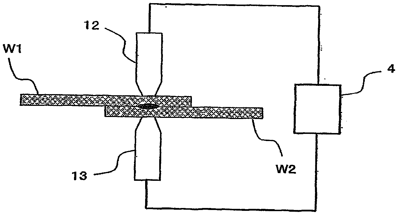
[0143] Two plates with a size of 100mm×25mm×2mm were prepared from the composite material and superimposed, and the superimposed part was clamped by electrodes. At this time, a copper electrode with a tip of Φ12 was used, and the applied force was 6.6kN (58.4MPa). In the pressurized state, a current of 60A was applied for 1 second from a DC power supply. The number of joints is 1.

[0144] (Evaluation)

[0145] The obtained bonded body was subjected to a tensile shear test at a speed of 1 mm / min using a 300 kN capacity floor-standing unive...

Embodiment 2

[0147] Two sheets of composite material same as in Example 1 were prepared and laminated, and clamped by a copper electrode with a front end of Φ5. The pressurization pressure is 3.4kN (173MPa), and the current of 60A is passed through the DC power supply for 2 seconds. The number of joints is 1.

[0148] (Evaluation)

[0149] The resulting bonded body was subjected to a tensile shear test at a speed of 1 mm / min using a 300 kN capacity floor-standing universal testing machine 5587 manufactured by Instron Corporation. The result was a breaking strength of 2.77 kN. It was confirmed that the obtained bonded body had no deformation such as warping.

Embodiment 3

[0151] (composite material)

[0152] Carbon fibers (Tenax STS40 manufactured by Toho Tenax Co., Ltd., average fiber diameter: 7 μm) with an average fiber length of 20 mm are randomly arranged and cut so that the average unit weight is 540 g / m 2 1. The weight ratio of carbon fiber is 52%, and the matrix is ​​made of UNITIKA nylon 6 manufactured by UNITIKA Co., Ltd. to make a carbon fiber composite material.

[0153] (fixed, powered up)

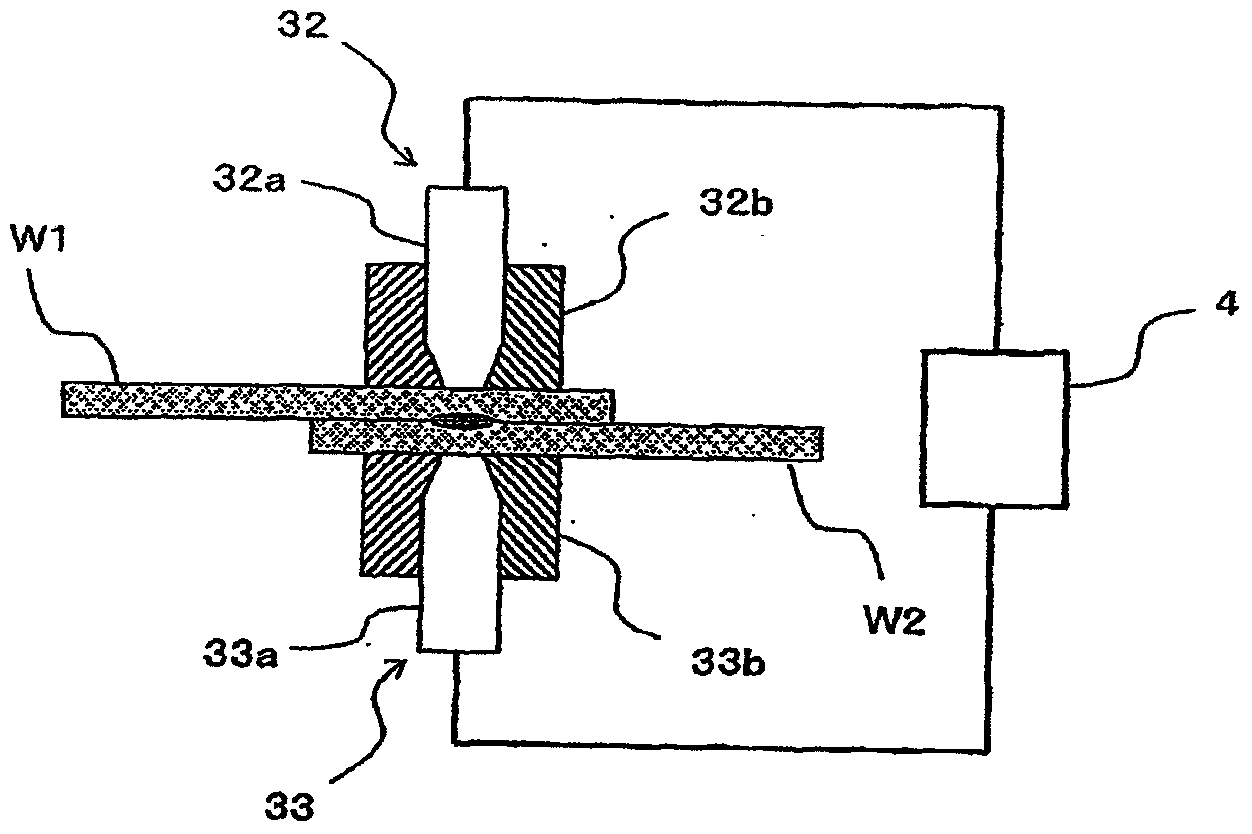
[0154] The composite material is used to prepare two plates with a size of 100mm×25mm×1.5mm and superimposed, and the superimposed part is clamped by electrodes. In this case, a Φ7 copper electrode is used on the inside, and a Φ16 fluororesin electrode with a pressurization assistant is used on the outside. The pressing force between the electrodes is 5.6kN (27.9MPa). Powered by a DC power supply in a pressurized state. In the first 0.5 seconds, the current value rises from 5A to 50A, and then remains energized at 50A for 1.5 seconds. The ...


PUM

PropertyMeasurementUnit
lengthaaaaaaaaaa
thicknessaaaaaaaaaa

Abstract

The purpose of the present invention is to provide a method for obtaining a joint in a short time and at a low current, the joint being very strong, exhibiting little deformation such as warping and being a composite material joint containing thermoplastic resin and carbon fibres. The present invention is a joint manufacturing method which includes each of the following processes: (i) preparing a plurality of composite materials including thermoplastic resin and discontinuous carbon fibres, in which the discontinuous carbon fibres are arranged in a random manner; (ii) overlaying the plurality of composite materials; (iii) sandwiching at least part of the overlapped portion between a pair of electrodes; and (iv) passing electric current between the electrodes, and solvent-welding the thermoplastic resin by means of Joule heat.

Description

technical field [0001] The present invention relates to a method for producing a joined body that joins composite materials that use thermoplastic resin as a matrix and contain discontinuous carbon fibers. Background technique [0002] In general, as a method of joining thermoplastic resin-based composite materials, connection by bolt-nuts and / or rivets, adhesives, welding, and the like can be mentioned. [0003] When connecting with bolt-nuts or rivets, it is necessary to drill holes in the base material. Therefore, there are problems such as lowering of base metal strength and increasing processing procedures. Moreover, although carbon fiber composite materials have attracted attention as a material with a weight-saving effect due to their strength and light weight in recent years, once the number of connection positions using bolt-nuts or rivets increases, the weight increases with the increase in connection parts. , thereby compromising the benefits of using carbon fib...

Claims


Application Information

Patent Timeline
Patent Type & Authority Applications(China)
IPC IPC(8): B29C65/02B23K11/06B23K11/00H01B1/24
CPCB29C66/949B29C66/91655B29C66/547B23K11/115B29C65/3468B29C65/38B23K2203/16H01B1/24B29C66/83221B29C66/91631B29C66/919B29C66/72143B29C66/944B29C66/929B29C66/1312B29C66/7212B29C66/73921B23K11/314B29C66/71B29C66/1122B29C66/81419B29C66/43B23K11/16B23K11/061B29C65/04B29C66/81875B29C66/21B32B27/34B29C66/73141B23K11/063B29C66/83413B29C65/3492B29C66/8322B29C65/3416B23K2201/18B29C66/9241B29C66/8122B29C66/81261B29C66/343B29C66/81463B23K2101/18B23K2103/16B23K2103/172Y10T428/24995Y10T428/31732B29K2023/06B29K2023/12B29K2077/00B29K2081/04B29K2069/00B29K2059/00B29K2025/06B29K2071/12B29K2067/003B29K2067/006B29K2033/12B29K2055/02B29K2307/04B29K2023/04B29K2023/10B29K2025/04B29K2827/18B29K2909/02B29K2067/00B29K2025/08B29C65/02B23K11/06B23K11/00
Inventor 加藤卓巳齐藤清小松秋男
Owner TEIJIN LTD
Learn More