Hydraulic circuit, method for operating same

A technology of hydraulic circuit and hydraulic medium, which is applied to non-mechanical drive clutches, elements with teeth, fluid drive clutches, etc., can solve the problems of poor clutch adjustment quality and achieve the effect of avoiding back pressure

Active Publication Date: 2014-02-05
AUDI AG
View PDF7 Cites 21 Cited by
  • Summary
  • Abstract
  • Description
  • Claims
  • Application Information

AI Technical Summary

Problems solved by technology

Here, the shared clutch cooling results in a poorer control quality of the clutches

Method used


Image

  • Hydraulic circuit, method for operating same
  • Hydraulic circuit, method for operating same

Examples


Embodiment Construction

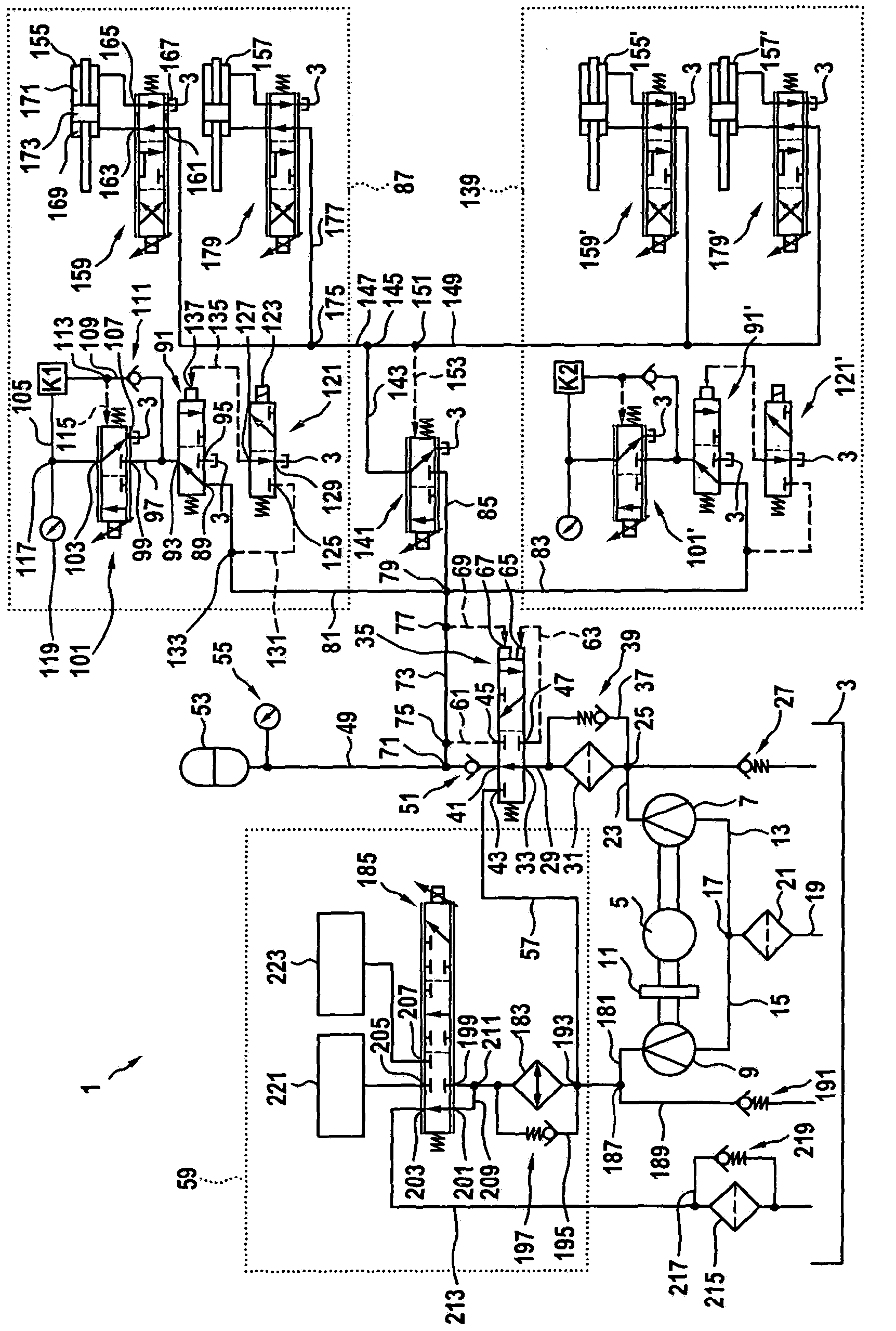
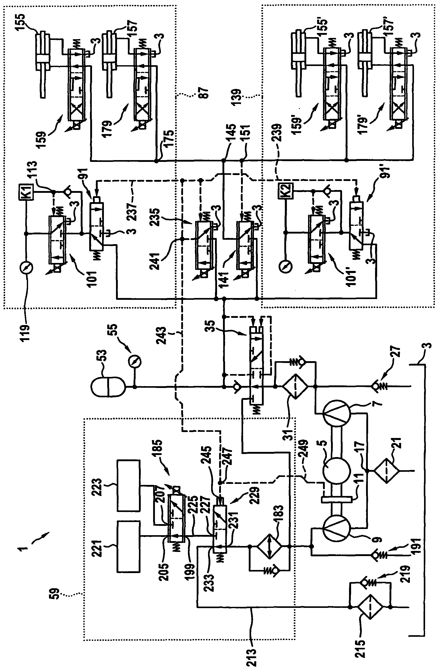
[0019] figure 1 A hydraulic circuit 1 is shown, which is used for cooling and actuating the dual-clutch transmission—in particular, coupling and engaging and disengaging gears. The hydraulic circuit 1 comprises a tank 3 which serves in particular as a storage container or reservoir for hydraulic medium for actuation and cooling, in which tank the hydraulic medium is stored preferably pressureless. An electric motor 5 is provided, which drives a first pump 7 and a second pump 9 . The electric motor 5 is preferably controllable, particularly preferably adjustable, with respect to its rotational speed and direction of rotation. The first pump 7 is fixedly connected to the electric motor 5 , ie no separating element is provided. This means that the pump 7 is always driven when the electric motor 5 is in operation and preferably delivers the hydraulic medium in a balanced manner in both directions of rotation. The pump 9 is preferably connected to the electric motor 5 via a sepa...


PUM


Abstract

The invention relates to a dual clutch transmission, especially of a motor vehicle, comprising a hydraulic circuit (1) for cooling the dual clutch transmission, said hydraulic circuit (1) comprising at least one pump (7, 9) for delivering a hydraulic fluid flow, at least one cooler (183) for cooling the hydraulic fluid flow, and a volume control valve (185) for adjusting the hydraulic fluid flow for at least one cooling system (221, 229) which is associated with clutches (K1, K2) of the dual clutch transmission. Said volume control valve (185) is designed such that it supplies the hydraulic fluid flow to a first cooling system (221), which is associated with a first one of the clutches (K1), in a first switching state and to a second cooling system (229), which is associated with a second one of the clutches (K2), in at least one second switching state.

Description

technical field [0001] The invention relates to a dual-clutch transmission, in particular a dual-clutch transmission of a motor vehicle, comprising a hydraulic circuit for cooling the dual-clutch transmission, said hydraulic circuit comprising at least one pump for delivering a flow of hydraulic medium, at least one for A cooler for cooling the hydraulic medium flow and a volume control valve for setting the hydraulic medium flow for at least one cooling device assigned to a clutch of the dual clutch transmission. [0002] The invention also relates to a method for operating a dual-clutch transmission, in particular a dual-clutch transmission as described above, with a hydraulic circuit for cooling the dual-clutch transmission, wherein a flow of hydraulic medium is delivered by means of a pump and by means of The cooler cools the hydraulic medium flow which is set for at least one cooling device assigned to a clutch of the dual clutch transmission by means of a volume control ...

Claims


Application Information

Patent Timeline
Patent Type & Authority Applications(China)
IPC IPC(8): F16H61/00F16H61/688
CPCF16H61/0021F16H61/688F16D25/14F16H57/0473F16H61/0206
Inventor D·舒勒H-P·弗雷施曼S·赫罗德
Owner AUDI AG
Why Eureka
Try Eureka