
Optical element

A technology of optical components and optics, applied in the direction of optical components, optics, optomechanical equipment, etc., can solve problems such as deformation of optical components

Active Publication Date: 2014-02-05
CARL ZEISS SMT GMBH
View PDF7 Cites 4 Cited by
  • Summary
  • Abstract
  • Description
  • Claims
  • Application Information

AI Technical Summary

Problems solved by technology

Spatially resolved thermal distribution can lead to undesired deformation of optics

Method used


Image

  • Optical element
  • Optical element
  • Optical element

Examples


Embodiment Construction

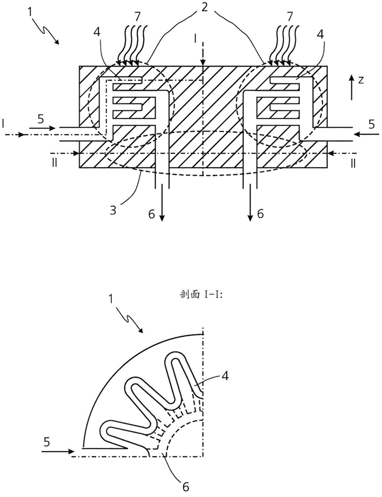
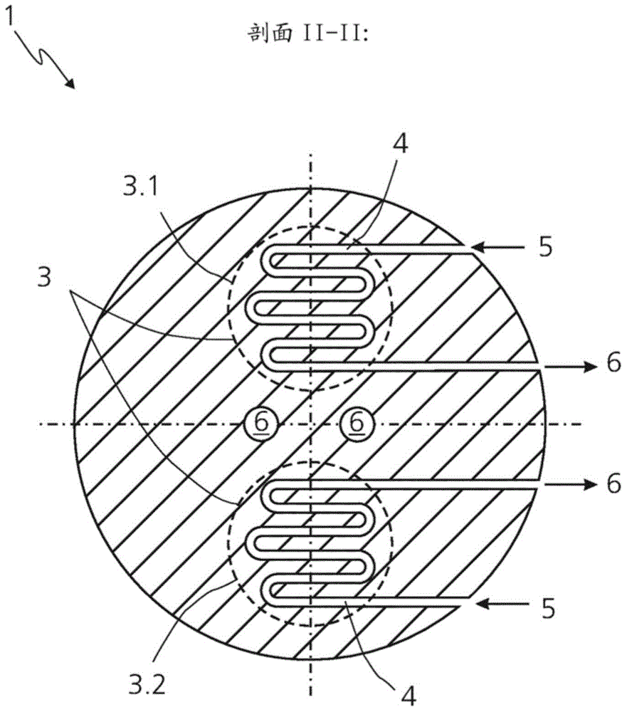
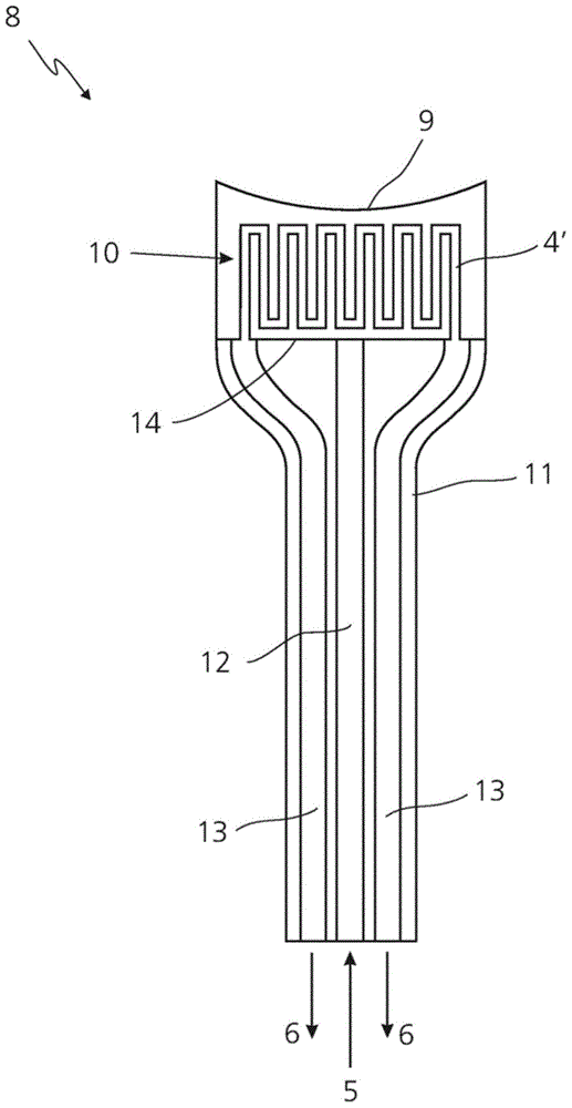
[0035] To spatially resolve these thermal distributions of the cooling optics, cooling bodies 1, 23 ( figure 1 , 2 and 5). The cooling body 1 shown can, for example, be fitted to a facet mirror or a deflecting mirror, or be implemented as a mirror carrier for an EUV deflecting mirror ( Figure 4 and 6 ). Figure 3a The possibility of incorporating microcoolers 10 into individual mirror facets 8 is shown.

[0036] figure 1 and figure 2 Shown is a cooling body 1 with cooling channels 4 leading into two cooling zones 2 and 3 , wherein the first cooling zone 2 is designed for annular heat loads and the second cooling zone 3 is designed for bipolar heat loads. figure 1 The optically active surface of the optical element is not shown, which is located in the region indicated by arrow 7 in the example shown. The cooling zone 3 is located in a deeper plane than the cooling zone 2 in the z-direction shown. In the heat sink 1 it is additionally possible to implement cooling cha...


PUM


Abstract

The invention relates to an optical element for a projection exposure apparatus for semiconductor lithography comprising an optically active surface (9) and at least one cooling component for cooling the optical element, wherein the cooling component is connected to at least two separate cooling circuits and embodied in such a way that the optically active surface (9) can be cooled to a greater extent in at least one partial region than in a further partial region. The invention furthermore relates to a projection exposure apparatus comprising an optical element according to the invention.

Description

technical field [0001] The invention relates to an optical element having at least one optically active surface. In this case, the optical element can especially be an optically separate component, such as a deflection mirror, in an EUV illumination system for semiconductor lithography. Likewise, an optical element can also consist of one or more optical individual components. For example, in the following, a facet mirror consisting of a mirror carrying body and a number of individual mirror facets is likewise referred to as an optical element. Background technique [0002] The mentioned optics are usually installed in larger units, such as EUV illumination systems. In this case, the optical element is a three-dimensional geometric body, which is usually delimited by a plurality of surfaces and which serves to fulfill one or more optical functions, such as the deflection or other manipulation of electromagnetic radiation. Depending on the beam path, the electromagnetic ra...

Claims


Application Information

Patent Timeline
IPC IPC(8): G03F7/20G02B7/195
CPCG02B7/1815G03F7/70891G02B5/0891G02B5/208
Inventor J.哈特杰斯D.菲奥尔卡B.普尼尼-米特勒
Owner CARL ZEISS SMT GMBH
Learn More