Embankment structure for reducing generation rate of bump at bridge head and filling method

A bridge head jumping and occurrence rate technology, which is applied to infrastructure engineering, roads, bridges, etc., can solve the problems of large manpower, material and financial resources for maintenance, difficulties in embankment drainage, waterproofing, and insufficient economic benefits, and achieve simple construction, Improved drainage consolidation conditions and low cost

Active Publication Date: 2014-02-12
HOHAI UNIV
View PDF7 Cites 9 Cited by
  • Summary
  • Abstract
  • Description
  • Claims
  • Application Information

AI Technical Summary

Problems solved by technology

[0004] The above method can solve the problem of jumping at the bridge head to a certain extent, but it also has its own shortcomings and deficiencies
For example, for the first type of disposal method, its construction is complicated, the cost is high, and the construction period is long, which has its shortcomings in terms of economic benefits
For the second type of disposal measures, in actual engineering, due to the limitations of construction and maintenance, it is still very difficult to achieve efficient embankment drainage and waterproofing. It is often a cyclical process of problem solving and problem solving, which is a passive processing method, resulting in a large amount of manpower, material and financial resources for post-operation maintenance

Method used


Image

  • Embankment structure for reducing generation rate of bump at bridge head and filling method
  • Embankment structure for reducing generation rate of bump at bridge head and filling method
  • Embankment structure for reducing generation rate of bump at bridge head and filling method

Examples


Embodiment Construction

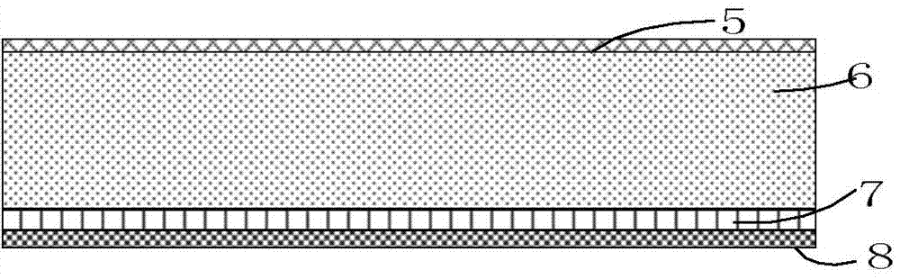
[0022] Such as Figure 1 to Figure 4 As shown, the embankment structure for reducing the incidence of vehicle jumping at the bridge head according to the present invention includes a cushion layer 8 , a stone layer 7 , an anti-jumping layer 6 , and a buffer layer 5 . The car jump layer is the main part of the main embankment, generally accounting for 60-90% of the total thickness of the embankment, preferably about 80+5%. For example, the height of the embankment is 5 meters, and the anti-jump layer is generally set to about 4 meters.

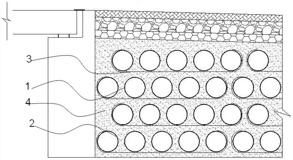
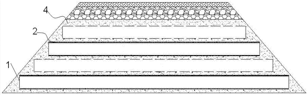
[0023] The anti-jumping layer includes several anti-jumping units and filler 4 filled around the anti-jumping units and between adjacent anti-jumping units. The anti-jumping unit includes a perforated pipe body 1 coated with a geotextile 2 on the outer periphery, a geogrid 3 connecting a certain number of perforated pipe bodies together, and a filler 4 filling the periphery of the perforated pipe body. The anti-jump units are multiple and dist...


PUM


Abstract

The invention discloses an embankment structure for reducing the generation rate of bump at a bridge head and a filling method. The embankment structure comprises an under layer, a stone layer, a bump-preventing layer and a buffer layer, which are sequentially arranged, wherein the bump-preventing layer comprises a plurality of bump-preventing units and fillers filled in the peripheries of the bump-preventing units and between the adjacent bump-preventing units; each bump-preventing unit comprises a pored pipe body of which the periphery is coated with geotechnical cloth, a geogrid for connecting a defined amount of pored pipe bodies together, and fillers filled in the peripheries of the pored pipe bodies. The filling method comprises the following steps: cleaning a field; laying the under layer of an embankment; laying a filler layer, and laying the geogrid on the filler layer; placing the pored pipe bodies coated with the geotechnical cloth on the geogrid; winding the geogrid on the defined amount of pored pipe bodies according to a certain spacing; repeating the step 5 for multiple times, and then filling soil and stone to be used as the buffer layer; and compacting. The embankment structure has the advantages of simplicity and convenience in construction, low cost, high economic benefit, good drainage condition, environmental friendliness, conservation and the like.

Description

technical field [0001] The invention relates to road and bridge engineering, in particular to an embankment structure and a filling method for reducing the incidence of vehicle jumping at the bridge head. Background technique [0002] Vehicle jumping at the bridge head is currently a common problem of road quality in my country. The vehicle jumping at the bridge head refers to the inconsistency between the settlement of the bridge abutment and the embankment at the junction of the bridge and the embankment, which leads to a wrong platform at the bridge head, causing the vehicle to drive in this position. Bumps and jumps occur. Especially with the rapid development of my country's high-grade highways in recent years, the phenomenon of vehicle jumping at the bridge head is particularly common. [0003] In view of the problem of vehicle jumping at the bridge head, there are two main existing treatment methods: one is to increase the strength of the bridge head foundation, mainl...

Claims


Application Information

Patent Timeline
Patent Type & Authority Applications(China)
IPC IPC(8): E01C3/00E02D19/12E01D21/00
Inventor 吴跃东罗如平石晓燕丁磊张鹏刁红国
Owner HOHAI UNIV
Why Eureka
Try Eureka