

Mixed shear connector
A shear-resistant connector and connector technology, which can be applied to buildings, building structures, etc., can solve problems such as difficulty in fitting calculation formulas, inconvenient application, etc., achieving good social benefits and transformation prospects, convenient connection, and reducing total cost. Effect
- Summary
- Abstract
- Description
- Claims
- Application Information
AI Technical Summary
Problems solved by technology
Method used
Image

Examples
Embodiment Construction
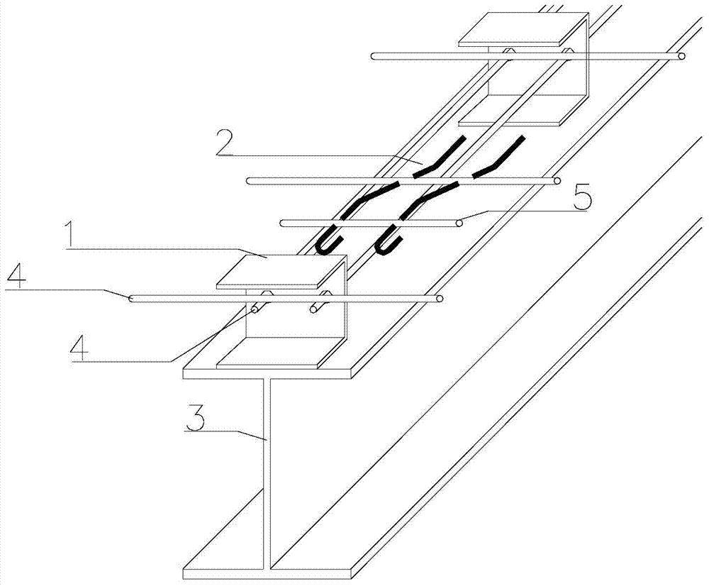
[0019] Below in conjunction with specific embodiment and accompanying drawing, the present invention will be further described:
[0020] Such as figure 1 As shown, a hybrid shear connector includes a channel steel connector 1 and a bent steel bar connector 2, the channel steel connector 1 and the bent steel bar connector 2 are arranged in the floor, the channel steel connector 1 and the bent steel bar connector 2 The bent steel bar connectors 2 are alternately arranged on the steel girder 3, the channel steel connectors 1 should be arranged at the beam end, the web of the channel steel connector 1 is provided with a reserved hole, and the longitudinal direction of the steel mesh in the floor slab Steel bars 4 pass through the reserved holes.
[0021] An additional transverse reinforcement 5 is added to the bent-up reinforcing bar connector, and is fastened with the bent-up reinforcing bar connector 2 .
[0022] The above is only a preferred embodiment of the present inventio...
PUM
 Abstract
Description
Claims
Application Information