Method of regenerating an exhaust aftertreatment device

A technology of exhaust post-processing and post-processing devices, which is applied in the direction of electronic control of exhaust treatment devices, exhaust devices, exhaust treatment, etc., can solve the problem of accurate fuel spray dissipation length, increase the interval of oil replacement, reduce Effects of engine degradation

Active Publication Date: 2017-05-10
FORD GLOBAL TECH LLC
View PDF7 Cites 0 Cited by
  • Summary
  • Abstract
  • Description
  • Claims
  • Application Information

AI Technical Summary

Problems solved by technology

However, the fuel spray dissipation length determined by delta pressure may not be as accurate as desired

Method used


Image

  • Method of regenerating an exhaust aftertreatment device
  • Method of regenerating an exhaust aftertreatment device
  • Method of regenerating an exhaust aftertreatment device

Examples


Embodiment Construction

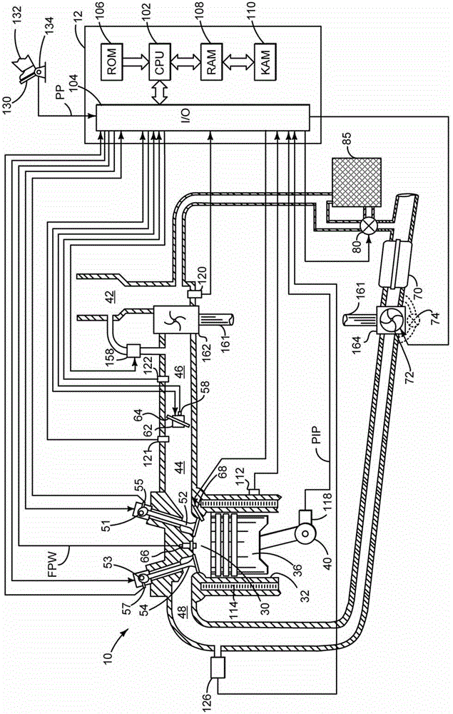
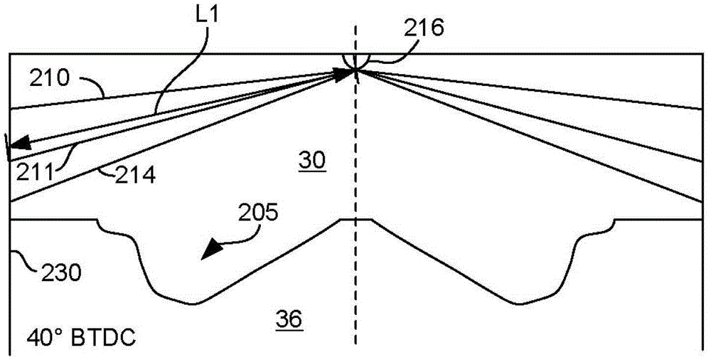
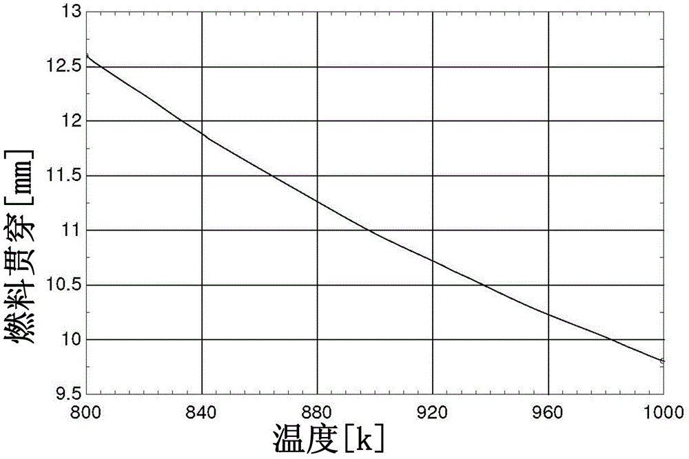
[0025] The present description relates to regenerating an exhaust aftertreatment device. figure 1 An example of a boosted diesel engine is shown, where Figure 4 A method of initiating aftertreatment device regeneration by controlling post-combustion fuel injection. figure 2 An example fuel injection through length is shown that provides a basis for the amount of fuel that may be injected to initiate aftertreatment device regeneration. Figure 3A-3B Shows how cylinder mixture density and temperature affect fuel injection penetration. At last, Figure 4 is an exemplary method for regenerating a particulate filter.

[0026] refer to figure 1 , an internal combustion engine 10 is controlled by an electronic engine controller 12, which includes a plurality of cylinders, one of which is shown in figure 1 middle. Engine 10 includes combustion chamber 30 and cylinder walls 32 with piston 36 positioned therein and connected to crankshaft 40 . Combustion chamber 30 is shown com...


PUM


Abstract

The invention relates to a method for regenerating an exhaust gas aftertreatment device. Methods and systems for regenerating an aftertreatment device are disclosed. In one example, the likelihood of introducing fuel into the oil during regeneration of the aftertreatment device is reduced. The method and system reduce engine degradation and improve engine emissions.

Description

technical field [0001] The present invention relates to methods of regenerating exhaust aftertreatment devices and related engine systems. Background technique [0002] Diesel engines have relatively high efficiency compared to other internal combustion engines. Higher engine efficiency produces lower engine exhaust temperatures. Lower exhaust temperatures can make regeneration of aftertreatment devices more difficult because aftertreatment devices tend to begin regeneration at higher temperatures. One way to create higher temperatures in the exhaust system is to inject fuel late in the cylinder cycle (eg, during the exhaust stroke) so that the fuel can oxidize in the exhaust system, raising exhaust system temperatures. However, when liquid fuel is injected during the exhaust stroke, some portion of the injected fuel may impinge in liquid form on the cylinder wall. Fuel that encounters cylinder walls in liquid form can degrade the oil film on the cylinder walls and increa...

Claims


Application Information

Patent Timeline
Patent Type & Authority Patents(China)
IPC IPC(8): F02D41/02F02D41/30
CPCF01N3/0871F01N9/002F01N2430/085F02D35/026F02D41/024F02D41/405F02D2250/11Y02T10/12Y02T10/40
Inventor E·库尔茨
Owner FORD GLOBAL TECH LLC
Why Eureka
Try Eureka