Stove for combined combustion of liquefied petroleum gas and methanol

A liquefied petroleum gas, two-in-one technology, applied in household stoves/stoves, lighting and heating equipment, etc., can solve the problems of increased combustion costs, large demand, environmental pollution, etc., and achieve high fuel combustion efficiency and stable combustion flames , Easy to install and use

Active Publication Date: 2014-02-12
盐城韩资工业园产业发展有限公司
View PDF5 Cites 0 Cited by
  • Summary
  • Abstract
  • Description
  • Claims
  • Application Information

AI Technical Summary

Problems solved by technology

[0002] At present, most hotels, restaurant kitchens and family kitchens use solid briquettes or petroleum liquefied gas. During the combustion of solid briquettes, soot and solid Residues, causing environmental pollution; while the cost of using liquefied petroleum gas is high, carbon monoxide poisoning is prone to occur in the case of incomplete combustion, and this fuel source has certain limitations, especially for some liquefied petroleum gas used in large quantities For major hotels and restaurants, the demand is large. On the one hand, it increases the cost of combustion, and on the other hand, it also has potential safety hazards; for this reason, people have developed a fuel that can use methanol, but methanol is liquid at room temperature. During the combustion process, the electric heating rod must be used to heat the liquid methanol first, so that the liquid methanol is vaporized, and then burns. In this way, the structure of the methanol stove is complicated and inconvenient to use

Method used


Image

  • Stove for combined combustion of liquefied petroleum gas and methanol

Examples


Embodiment Construction

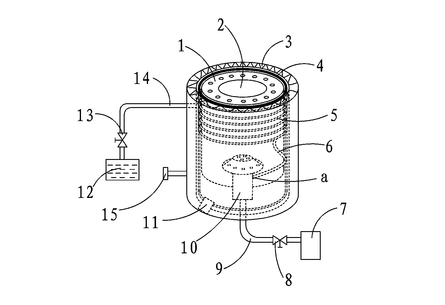
[0013] Such as figure 1 As shown, the methanol stove with improved structure is mainly composed of a furnace body 1, an insulating layer 3 surrounding the furnace body 1, a copper tube 5 wound on the outer wall of the furnace body 1, and a furnace core located at the center of the furnace body 1 to burn Chamber 10 is composed.

[0014] A layer of heat insulation layer 4 may also be provided between the furnace body 1 and the insulation layer 3 to prevent the heated copper tube 5 from diffusing heat outward, so as to ensure that sufficient heat is stored in the copper tube 5 .

[0015] The lower end of the furnace core combustion chamber 10 is connected with the petroleum liquefied gas hose 9, and the petroleum liquefied gas hose 9 is provided with a gas control valve 8; the lower end of the furnace core combustion chamber 10 is also provided with a methanol gas pipeline inlet a, and the furnace core burns A plurality of gas shower heads 2 are arranged inside the chamber 10, a...


PUM


Abstract

The invention discloses a stove for combined combustion of liquefied petroleum gas and methanol. The stove is mainly composed of a stove body, a heat preservation layer enclosed on the surrounding of the stove body, a copper pipe wound on the outer wall of the stove body and a stove core combustion chamber arranged at the center of the stove body, wherein the lower end of the stove core combustion chamber is connected with a liquefied petroleum gas hose, and a gas control valve is arranged on the liquefied petroleum gas hose; a methanol gas pipeline inlet is also formed in the lower end of the stove core combustion chamber, and a gas combustion spray head is arranged on the end part of the stove core combustion chamber; the starting end of the copper pipe wound on the outer wall of the stove body is connected with a methanol liquid conveying pipe, the tail end of the copper pipe wound on the outer wall of the stove body is connected with a methanol gas conveying pipe, and the other end of the methanol gas conveying pipe is connected with the methanol gas pipeline inlet in the stove core combustion chamber. The stove disclosed by the invention is both used as a common liquefied petroleum gas stove and a methanol stove to realize dual purpose of the stove so as to fully save the energy source, and the combustion efficiency of fuels is high; meanwhile, when methanol gas is burnt, the flame of the stove is stable, the flame helically ascends, and the stove is free of odor or pollution, low in manufacturing cost and convenient to install and use.

Description

technical field [0001] The invention belongs to a combustion stove, in particular to a dual-purpose stove capable of burning petroleum liquefied gas and methanol. Background technique [0002] At present, most of the major hotels, restaurant kitchens and family kitchens use solid briquettes or petroleum liquefied gas. During the combustion of solid briquettes, soot and solid residues are produced, causing environmental pollution; while petroleum liquefied gas is expensive to use. In the case of incomplete combustion, carbon monoxide poisoning is prone to occur, and this fuel source has certain limitations, especially for some major hotels and restaurants that use a large amount of petroleum liquefied gas, the demand is large, on the one hand, it will increase Combustion costs, on the other hand, there are also potential safety hazards; for this reason, people have developed a fuel that can use methanol, but methanol is liquid at room temperature. After the methanol is gasi...

Claims


Application Information

Patent Timeline
Patent Type & Authority Applications(China)
IPC IPC(8): F24C11/00
Inventor 徐晓阳
Owner 盐城韩资工业园产业发展有限公司
Why Eureka
Try Eureka