Device and method for oxygen and nitrogen separation through air and rapid increase of pressure nitrogen loads

An air separation and pressure increase technology, which is applied in the field of devices that separate oxygen and nitrogen from air to rapidly increase the pressure and nitrogen load, can solve the problems of large equipment investment, cumbersome operation and increase equipment investment, etc.

Active Publication Date: 2014-02-12
CHINA PETROLEUM & CHEM CORP
View PDF6 Cites 6 Cited by
  • Summary
  • Abstract
  • Description
  • Claims
  • Application Information

AI Technical Summary

Problems solved by technology

[0003] The above method basically satisfies the demand of the production plant for nitrogen, but we can easily see from it that the first method needs to increase the design scale of the oxygen and nitrogen output of the air separation plant, increase the investment in equipment, and at the same time, a large part of it is usually vented Quantity (after all, the production device is in normal operation most of the time), the natural operating cost increases
The second method needs to configure a liquid nitrogen storage tank and a liquid nitrogen vaporization system in addition to the air separation device, which is also a large investment in equipment and occupies a certain space. The key is the operation of the current liquid nitrogen vaporization system. It is cumbersome, and there is a certain gap when dealing with equipment emergencies. The vaporization of liquid nitrogen generally takes more than 20 minutes from the start of operation to the delivery of nitrogen gas.

Method used


Image

  • Device and method for oxygen and nitrogen separation through air and rapid increase of pressure nitrogen loads

Examples


Embodiment Construction

[0064] The present invention will be further described below in conjunction with the accompanying drawings and specific embodiments.

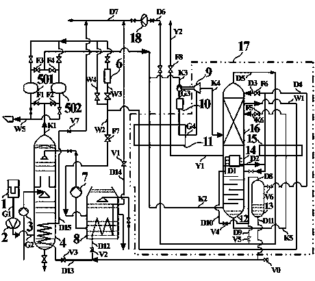
[0065] Such as figure 1 As shown, a device for rapidly increasing pressure nitrogen load by separating oxygen and nitrogen from air, including:

[0066] Filter (1), compressor (2), normal temperature water pump (3), air cooling tower (4), first molecular sieve adsorber (501), second molecular sieve adsorber (502), heater (6), Low temperature water pump (7), water cooling tower (8), booster expander (9), heat exchanger (10), main heat exchanger (11), lower tower (12), main condensing evaporator (14), Cold liquefier (15), upper tower (16), cold box (17), nitrogen compressor (18),

[0067] Liquid nitrogen bare tank (13), the first liquid nitrogen vaporizer, the second liquid nitrogen vaporizer,

[0068] Liquid nitrogen enters or exits the liquid nitrogen bare tank valve (V0), the water cooling tower liquid nitrogen vaporization outlet control v...


PUM


Abstract

The invention provides a device and a method for oxygen and nitrogen separation through air and rapid increase of pressure nitrogen loads. According to the device and the method for oxygen and nitrogen separation through air and rapid increase of the pressure nitrogen loads, on the basis of a full low pressure external compression air separation process, according to a condition of peripheral requirement for pressure nitrogen, a liquid nitrogen bare tank with an appropriate volume is arranged in an ice box of an air separation device to be used for storing redundant liquid nitrogen of the air separation device during a normal production period; the liquid nitrogen bare tank and a liquid nitrogen vaporizer valve and pipelines which are arranged at bottoms of a water cooling tower and an air cooling tower are in organic connection with the air separation device to enable the liquid nitrogen inside the liquid nitrogen bare tank to be rapidly vaporized when external supplied nitrogen is increased suddenly and generate small disturbance to production working conditions of an original air separation device. The device and the method for oxygen and nitrogen separation through air and rapid increase of the pressure nitrogen loads have the advantages of enabling pressure nitrogen outside delivered loads to be increased by 100 % in few minutes to enable accidents of a production device to be coped with, solving the problem of increase of sudden pressure nitrogen loads, reducing nitrogen yield redundancy when a novel air separation device is designed and enabling energy consumption of the air separation device during the normal operation period to be reduced.

Description

technical field [0001] The invention belongs to the field of cryogenic air separation of oxygen and nitrogen, and relates to a device and method for fully low-pressure externally compressed air separation, in particular to a device and method for air separation of oxygen and nitrogen to quickly increase the pressure nitrogen load. Background technique [0002] In large-scale petrochemical complexes, nitrogen is used as a protective gas in many production devices for purposes such as machine sealing, tank replacement, material transportation, heating regeneration, equipment purging, etc. To avoid the expansion of the accident, it is necessary to spray nitrogen urgently to play the role of isolation, flame retardancy, and dilution of materials. At present, the air separation unit usually separates the oxygen and nitrogen in the air through the full low pressure and low temperature, and provides it to the downstream equipment. The output load of the air separation unit is gener...

Claims


Application Information

Patent Timeline
Patent Type & Authority Applications(China)
IPC IPC(8): F25J3/04
CPCF25J3/04157F25J3/04303F25J3/04412F25J3/04836F25J2205/32F25J2205/34F25J2230/42F25J2245/42F25J2245/90F25J2250/42F25J2270/904
Inventor 常兴路
Owner CHINA PETROLEUM & CHEM CORP
Why Eureka
Try Eureka