
Method and device for material drying by means of porous media

A technology of porous media and materials, applied in the direction of promoting the drying of solid materials, drying solid materials, heating to dry solid materials, etc., can solve the problems of poor drying effect, long drying time, high cost, etc., and achieve the goal of drying methods and Simple device, good drying effect and large output

Active Publication Date: 2015-05-13
HENAN POLYTECHNIC UNIV
View PDF10 Cites 0 Cited by
  • Summary
  • Abstract
  • Description
  • Claims
  • Application Information

AI Technical Summary

Problems solved by technology

At present, most of the high-temperature flue gas generated by fuel combustion is used as a heat source to dry materials. This method not only requires a large investment and high cost, but also causes environmental pollution.
Another way is to use the method of drying in a solar greenhouse, which takes a long time to dry. If it is combined with other heat sources for drying, the space will be larger and the heat loss will be serious.
For different types of materials, when the moisture content of the material is higher than a certain value, even after reverse mixing, it cannot effectively avoid its adhesion on the surface of the turning device. At this time, the wet material is wrapped on the surface of the dry material and sticks into large groups, resulting in turning over. The throwing machine can't play the role of turning and throwing, which seriously affects the drying effect of the material
Secondly, for materials with very small particle size, the bulk density is relatively high and the surface pores are few, resulting in a small contact surface area with hot air, which cannot achieve sufficient contact between hot air and materials, which affects the effect of convective heat transfer
Furthermore, air is generally used as the main drying medium, and air has a small specific heat capacity and has no heat storage capacity, resulting in poor drying effect in a large space.

Method used


Image

  • Method and device for material drying by means of porous media
  • Method and device for material drying by means of porous media

Examples


Embodiment Construction

[0022] The present invention will be described in further detail below in conjunction with the accompanying drawings.

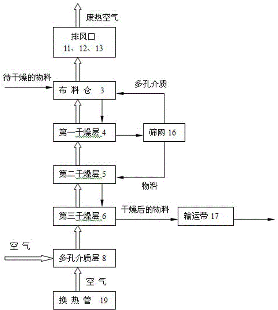
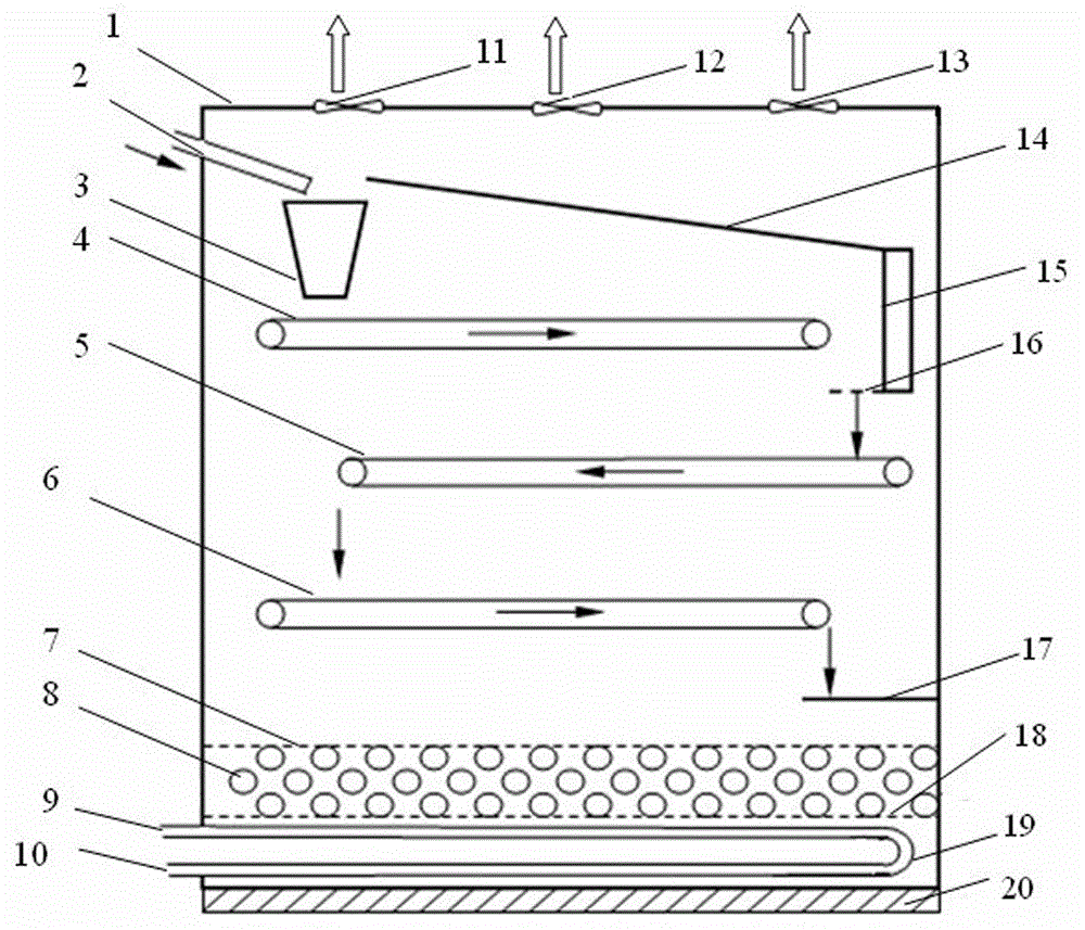
[0023] like figure 1 , 2 As shown, the method is that the hot air and the material adopt a countercurrent heat exchange method, and the material to be dried enters the material distribution bin 3 through the material inlet pipe 2 to be mixed with the porous medium, and is mixed and stirred to achieve uniform mixing. The material to be dried and the porous medium are mixed. The mixture fully contacts and exchanges heat with the hot air from the second drying layer 5 in the first drying layer 4. The material in the first drying layer 4 has a high moisture content, and mixing with porous media can expand the contact surface area with the air and loosen the material to be dried. And form pores in the material layer, which is conducive to the passage of hot air in the second drying layer 5, and at the same time fully contact with the material to exchange heat an...


PUM

PropertyMeasurementUnit
diameteraaaaaaaaaa
thicknessaaaaaaaaaa
thicknessaaaaaaaaaa

Abstract

The invention discloses a method and device for drying materials by using porous media, which adopts a countercurrent method to dry materials, and the materials to be dried in the drying bin and the porous media are mixed into the first drying layer and come from the second drying layer in the distribution bin. The hot air fully contacts the heat exchange, absorbs heat, and evaporates the water to dry the material; the waste hot air passing through the first drying layer is discharged from the drying chamber; the mixture of the material and the porous medium passing through the first drying layer enters the screen device, and passes through After sieving, the material is separated from the porous medium, and the porous medium returns to the distribution bin to mix with the material to be dried; the material passing through the first drying layer enters the second drying layer and contacts with the hot air from the third drying layer to exchange heat, and in the third drying layer Contact with hot air to exchange heat, and when the final moisture content requirement is reached, it will be transported out of the drying bin. The invention especially solves the problem of drying viscous materials, and its drying method and equipment are relatively simple, which can realize high efficiency and energy saving in the material drying process.

Description

technical field [0001] The invention relates to a method and device for drying viscous materials, in particular to a method and device for realizing material drying by using porous media. Background technique [0002] According to statistics, drying energy consumption accounts for about 30% of the total energy consumption of the national economy, especially viscous materials such as municipal or chemical sludge, which have high viscosity, long drying cycle and high heat consumption. At present, most of them use high-temperature flue gas generated by fuel combustion as a heat source to dry materials. This method not only requires large investment and high cost, but also causes environmental pollution. Another way is to use the method of drying in a solar greenhouse, which takes a long time to dry. If it is combined with other heat sources for drying, the space will be larger and the heat loss will be serious. For different types of materials, when the moisture content of the...

Claims


Application Information

Patent Timeline
Patent Type & Authority Patents(China)
IPC IPC(8): F26B3/06F26B1/00F26B17/00F26B25/00C02F11/10
Inventor 王华余晓雷王红星邹家宁张明军张小明邢道明
Owner HENAN POLYTECHNIC UNIV
Learn More