Pressure transmitter for locomotive braking system

A braking system and transmitter technology, applied in instruments, force/torque/work measuring instruments, measuring devices, etc., can solve the problems of serious mutual interference between devices, being susceptible to external interference, and weak anti-electromagnetic interference ability, etc. To achieve the effect of reducing interference, facilitating assembly, and improving anti-interference ability

Active Publication Date: 2016-06-29
NINGBO CRRC TIMES TRANSDUCER TECH CO LTD
View PDF9 Cites 0 Cited by
  • Summary
  • Abstract
  • Description
  • Claims
  • Application Information

AI Technical Summary

Problems solved by technology

[0003] The signal conditioning circuit is used in the modular circuit of the pressure transmitter used in the existing locomotive brake system, which can realize the mutual conversion between different types of signals, so that the devices with different input and output can be used together. However, due to the signal conditioning The composition of the circuit is quite rich, there are both high-speed circuits and low-speed circuits, both digital circuits and analog circuits, and various devices are distributed in a relatively small space, and the mutual interference between devices is very serious. The circuit deals with weak signals and is extremely susceptible to external interference, so its ability to resist electromagnetic interference is weak, which affects the use of the product
The existing anti-interference technical means mainly include rational design of printed circuit board wiring, filtering to suppress conduction interference, shielding and suppression of radiation anti-interference, etc. Although these technical means also have certain effects, the design is difficult and the cost is high

Method used


Image

  • Pressure transmitter for locomotive braking system
  • Pressure transmitter for locomotive braking system
  • Pressure transmitter for locomotive braking system

Examples


Embodiment Construction

[0025] The present invention will be further described below in conjunction with accompanying drawings and embodiments.

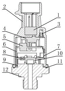
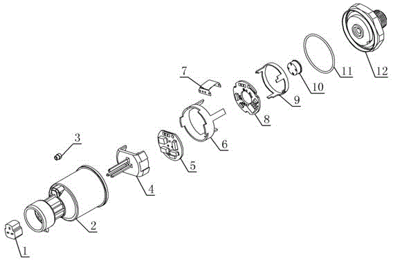
[0026] Such as figure 2 , image 3 The pressure transmitter shown in the locomotive brake system includes a rubber plug 1, a housing 2, a waterproof and breathable plug 3, a pin assembly 4, a power board 5, an upper bracket 6, a flexible circuit board 7, a signal board 8, a lower Bracket 9 , sensor core 10 , O-ring 11 , base 12 .

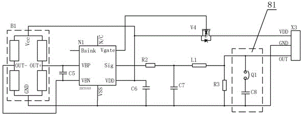
[0027] In order to improve the electromagnetic compatibility and anti-interference ability of the pressure transmitter, the power board 5 and the signal board 8 in the housing 2 are isolated from each other, the power circuit is integrated in the power board 5, the signal processing circuit is integrated in the signal board 8, and the power board 5 It is electrically connected with the signal board 8 by the flexible circuit board 7, so that the power board 5 and the signal board 8 are set separately, which can reduce the impac...


PUM


Abstract

The invention discloses a pressure transmitter for a locomotive braking system, which comprises a housing, a base, and a sensor core inside the housing. A power board and a signal board isolated from each other are arranged in the housing. The power board and the signal board are composed of a flexible The circuit board is electrically connected, the signal board is electrically connected to the sensor core, the power supply board is integrated with a power circuit to supply power for the pressure transmitter, the signal board is integrated with a signal processing circuit, and the conditioning chip in the signal processing circuit processes the signal detected by the sensor core. Pressure signal, and output the processed signal. The signal board is also integrated with a communication locking line. The communication locking line is set between the signal output end of the signal processing circuit and the grounding end. The communication locking line is a connecting point where capacitors can be connected in series. . The power board and signal board are isolated, which can reduce the interference between the circuits, improve the anti-interference ability and electromagnetic compatibility, and the two ends connected to the docking point can lock the communication port of the conditioning chip.

Description

technical field [0001] The invention relates to a pressure transmitter, in particular to a transmitter used for testing the pressure of a locomotive brake system. Background technique [0002] Pressure transmitter is the most commonly used sensor in industrial practice, suitable for industrial self-control environment, used to measure the pressure of liquid, gas or steam, etc. The pressure transmitter is mainly composed of a load cell sensor, a module circuit, a display head, a watch case and connectors, etc. It can convert the gas, liquid and other pressure signals received by the load cell sensor into a standard current and voltage signal. [0003] The signal conditioning circuit is used in the modular circuit of the pressure transmitter used in the existing locomotive brake system, which can realize the mutual conversion between different types of signals, so that the devices with different input and output can be used together. However, due to the signal conditioning Th...

Claims


Application Information

Patent Timeline
Patent Type & Authority Patents(China)
IPC IPC(8): G01L5/28
Inventor 张曙坚张燕亮张林伟姚福龙夏状东余建君
Owner NINGBO CRRC TIMES TRANSDUCER TECH CO LTD
Why Eureka
Try Eureka