Optical module and scanning type image display device

A technology of optical modules and optical components, applied in optics, optical components, installation, etc., can solve the problems of optical axis offset, no hints, etc., to increase the area, prevent peeling, and reduce the deviation of the relative position of the light spot Effect

Inactive Publication Date: 2014-02-12
HITACHI MEDIA ELECTORONICS CO LTD
View PDF7 Cites 3 Cited by
  • Summary
  • Abstract
  • Description
  • Claims
  • Application Information

AI Technical Summary

Problems solved by technology

[0017] Although Patent Documents 2 and 3 describe the position of the adhesive, they neither disclose nor suggest the following technical problems: adhesion due to curing shrinkage of the adhesive or temperature rise during use of the scanning image display device. Expansion of the agent, or expansion or contraction of the adhesive due to changes in the ambient temperature when the scanning image display device is used, force is applied to the optical components, the optical components are displaced, and the optical axis is shifted.

Method used


Image

  • Optical module and scanning type image display device
  • Optical module and scanning type image display device
  • Optical module and scanning type image display device

Examples


Embodiment 1

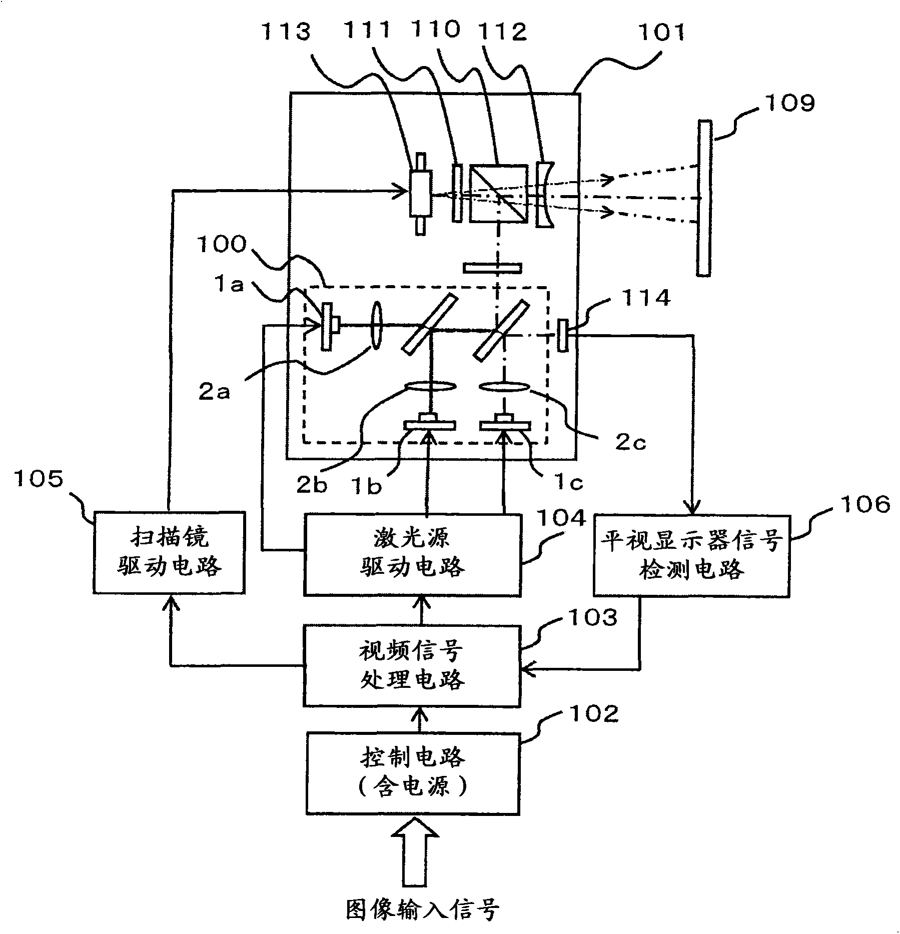
[0049] figure 1 It is a configuration diagram of a scanning image display device according to an embodiment of the present invention.

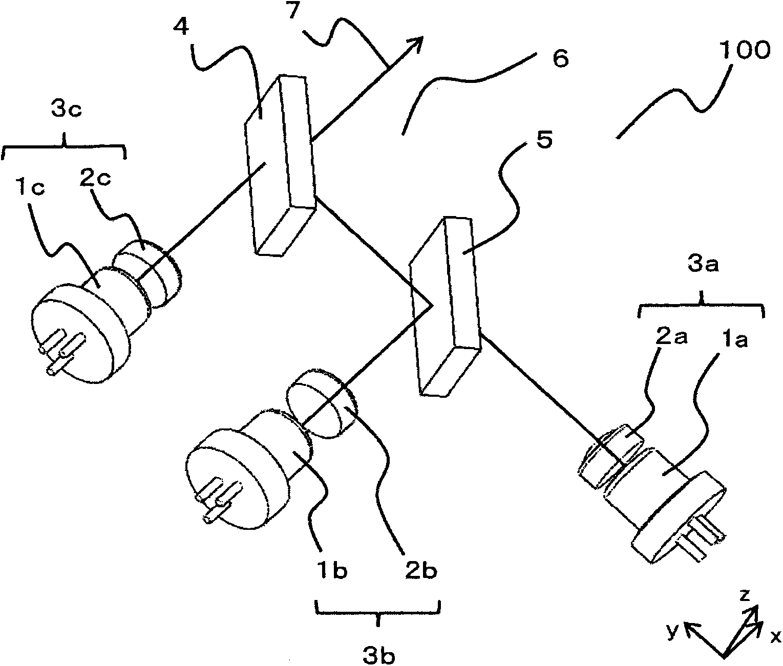
[0050] exist figure 1 Among them, the optical module 101 has: a laser source module 100, which has: a first laser 1a, a second laser 1b, The third laser 1c; and the beam coupling part, which makes the beams emitted from each laser source and passed through the first lens 2a, the second lens 2b, and the third lens 2c of the so-called collimating lens be optically coupled; A projection unit that projects the beam light onto the screen 109 ; and a scanning unit that two-dimensionally scans the projected beam light on the screen 109 . The projection unit includes a polarizing beam splitter (PBS) 110 , a 1 / 4 wave plate 111 , an angle of view enlarging element 112 , and the like. In addition, the scanning unit includes a scanning mirror 113 and the like.

[0051] An image input signal to be displayed is input to a video signal processing circuit...

Embodiment 2

[0082] Figure 6 It is a sectional view showing the second embodiment of the mounting structure of the optical components of the optical module of the present invention.

[0083] use image 3 , Figure 4 When the mounting configuration 200 of the optical component is shown, displacement and rotation of the optical component are suppressed. When there is an adhesive between the slope 13a of the optical component holder 10a and the slope 15a of the housing 14, the adhesive may drip from the narrow portion 400a between the slope 13a and the slope 15a. For dripping adhesive, by using Figure 6 The mounting structure 201 of optical components as shown can suppress displacement and rotation of the lens 2a.

[0084] In the optical component mounting structure 201, the first lens 402a is held by the optical component holder 410a for holding the first lens 402a.

[0085] On the optical component holder 410a, an inclined surface 413a and an inclined surface 413b are provided symmet...

Embodiment 3

[0095] Figure 7 It is a cross-sectional view showing a third embodiment of the mounting structure of the optical components of the optical module of the present invention.

[0096] The difference from Embodiment 1 and Embodiment 2 is that the slope 13a and the slope 13b of the optical component holder 10a adopt the curved surface 501a and the curved surface 501b, and the slope 15a and the slope 15b of the housing 14 adopt the curved surface 502a and the curved surface 502b. The curvatures of the curved surface 501 a , the curved surface 501 b , the curved surface 502 a , and the curved surface 502 b are the same, and the central axes of the curved surfaces are parallel to the optical axis 11 a of the lens 2 . The curved surface 501a of the optical component holder 10a and the curved surface 502a of the housing 14 are symmetrical with respect to the second symmetrical plane 16a passing through the center of the gap between the curved surface 501a and the curved surface 502a an...


PUM


Abstract

An optical module including a case to hold the optical module, and two sloped surfaces symmetrically formed to enclose a first surface including the optical axis of the optical component in an optical component holder retaining a portion of the optical component, a sloped surface is formed in the case at one position each so as to be formed opposite to the sloped surfaces at two positions of the optical component or optical component holder, and the one sloped surface of the optical component or optical component holder and the one sloped surface of the case at opposite side are symmetrical to the second surface parallel to the first surface and including the side intersecting the surface extending from the sloped surface of the case and the sloped surface of optical component or optical component holder, and the section between these sloped surfaces contains adhesive.

Description

technical field [0001] The present invention relates to an optical module and a scanning image display device, and more particularly, to an optical module that emits beams from a plurality of lasers aligned on one optical axis, and a scanning image that displays an image of the beams from the optical module display device. Background technique [0002] In recent years, the development of compact projectors that are portable and can display on a large screen has been vigorously developed. Camcorders with built-in compact projectors that can be connected to laptops, etc., or projectors that can project and store images are already on the market, and it is expected that projectors built into mobile phones and smartphones will appear in the future. [0003] Previously, there was a type of projector that used a lamp or LED as a light source to project an image displayed on a liquid crystal panel or a digital micromirror device (DMD), but lasers are also being used as a light sou...

Claims


Application Information

Patent Timeline
Patent Type & Authority Applications(China)
IPC IPC(8): G02B27/10G02B7/02G02B26/10
CPCG02B7/023G02B7/025G02B7/028G02B26/101G02B27/104G02B27/1053G02B26/10
Inventor 加藤盛一风间敦龟泽征彦田中哲平保坂宪生
Owner HITACHI MEDIA ELECTORONICS CO LTD
Why Eureka
Try Eureka