Dual-polarized antenna having the same main beam radiation feature

An antenna system, vertically polarized antenna technology, applied to antenna unit combinations, antennas, antenna arrays and other directions with different polarization directions, can solve problems such as not so easy

Active Publication Date: 2014-02-12
康凯科技(杭州)股份有限公司
View PDF3 Cites 7 Cited by
  • Summary
  • Abstract
  • Description
  • Claims
  • Application Information

AI Technical Summary

Problems solved by technology

Although it is not difficult to design an antenna system that provides both horizontally and vertically polarized RF links, it is not so easy to make the main beam radiation characteristics of the two polarizations basically the same

Method used


Image

  • Dual-polarized antenna having the same main beam radiation feature
  • Dual-polarized antenna having the same main beam radiation feature
  • Dual-polarized antenna having the same main beam radiation feature

Examples


Embodiment Construction

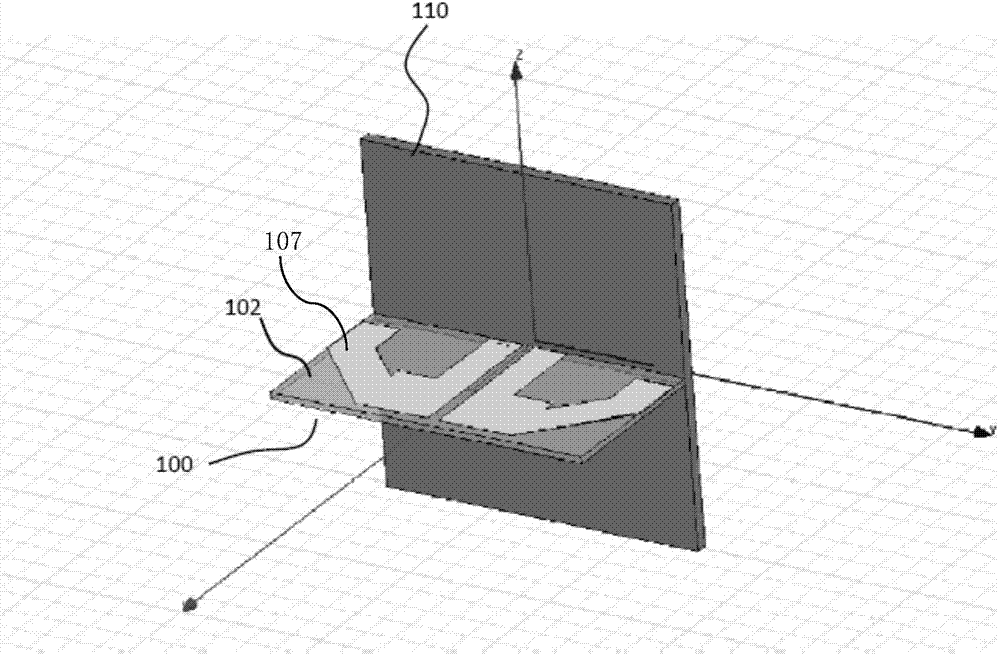
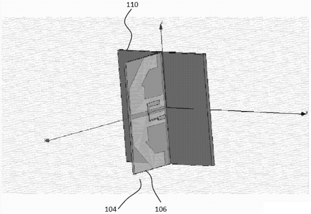
[0033] The detailed description of the present invention includes procedures, steps, logical operations, processing and other similar operations that use symbols to directly or indirectly indicate the coupling between the communication device and the feeding network. Descriptions of these procedures are typically used by those skilled in the art to communicate effectively with others skilled in the art.

[0034] "A specific embodiment" or "a specific embodiment" used in the following description refers to a specific embodiment that combines specific features, structures or characteristics described in the specific embodiment and is at least included in the present invention. The appearance of "in a specific embodiment" does not necessarily refer to the same specific embodiment, and these specific embodiments do not mutually exclude or replace each other. In addition, the order of the specific embodiments mentioned in the flow chart in this embodiment does not represent any spe...


PUM


Abstract

The invention discloses an antenna system, comprising a substrate, and a plurality of antenna units which are arranged in a predetermined geometric pattern and are connected to the substrate. Each antenna unit includes a horizontally polarized antenna and a vertically polarized antenna. The horizontally polarized antenna or the vertically polarized antenna of the antenna unit is stimulated based on instruction and the antenna type signal adopting the antenna system, and thereby better wireless link can be provided to the communication device.

Description

technical field [0001] The present invention relates to the field of antennas, and more particularly to an antenna array that is electronically controlled to form a desired antenna pattern, wherein two independently polarized antenna elements can be electrically controlled to form the same main beam radiation characteristic. Background technique [0002] The antenna system is essential in the composition of the communication system. In existing wireless communications, a single antenna is used for the transmitting source and the receiving end respectively. In physics, an antenna is an electrical device that provides conversion between electrical energy and radio frequency electromagnetic waves, and is usually used in a wireless transmitter or receiver. When transmitting, the wireless transmitter sends an oscillating radio frequency current to the antenna, and the antenna converts it into electromagnetic waves to radiate; when receiving, the antenna intercepts a part of the...

Claims


Application Information

Patent Timeline
Patent Type & Authority Applications(China)
IPC IPC(8): H01Q21/24H01Q1/38H01Q1/36
CPCH01Q21/062H01Q25/001
Inventor 李鑫郑博信汪义兵沈骏赵辉
Owner 康凯科技(杭州)股份有限公司
Why Eureka
Try Eureka