High lift system for an aircraft

An aircraft and lift technology, applied in the field of lift systems, to achieve low maintenance costs and weight savings

Active Publication Date: 2014-02-12
AIRBUS OPERATIONS GMBH
View PDF4 Cites 4 Cited by
  • Summary
  • Abstract
  • Description
  • Claims
  • Application Information

AI Technical Summary

Problems solved by technology

[0008] Additionally, the required redundancy may require multiple parts
A coupling gear unit connecting the two drive trains may also be necessary, but this results in additional weight
If there is a fault, the high-lift system may only be able to continue at reduced speeds

Method used


Image

  • High lift system for an aircraft
  • High lift system for an aircraft
  • High lift system for an aircraft

Examples


Embodiment Construction

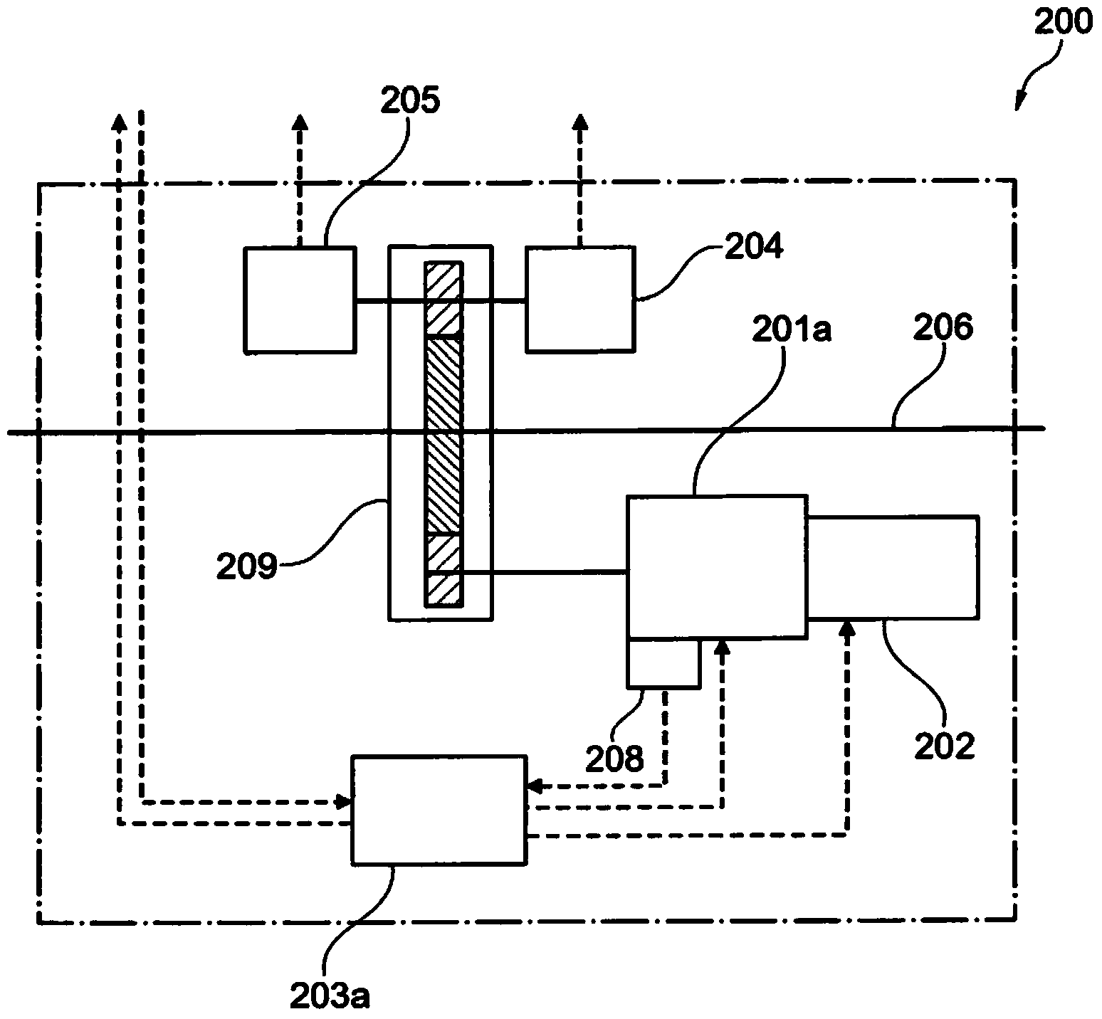
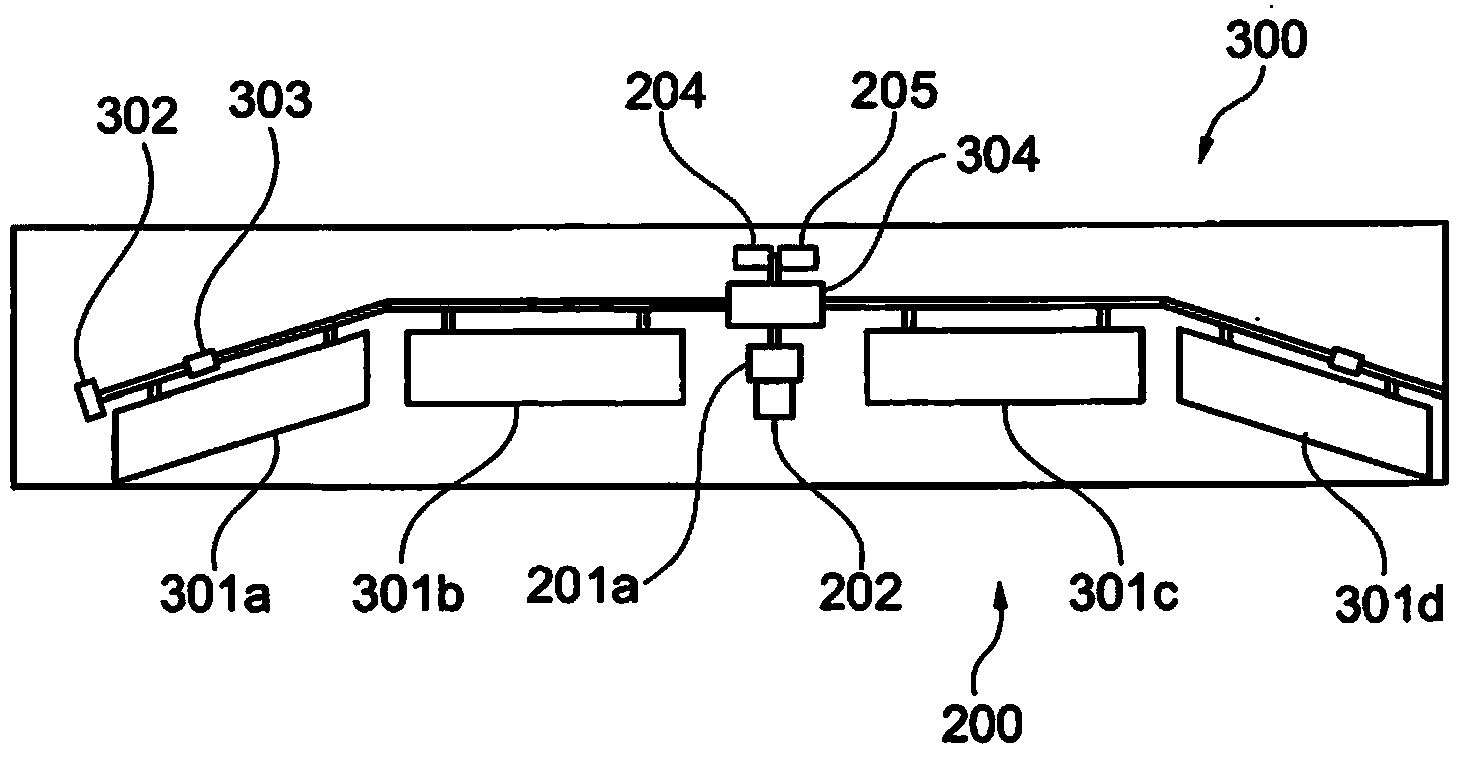
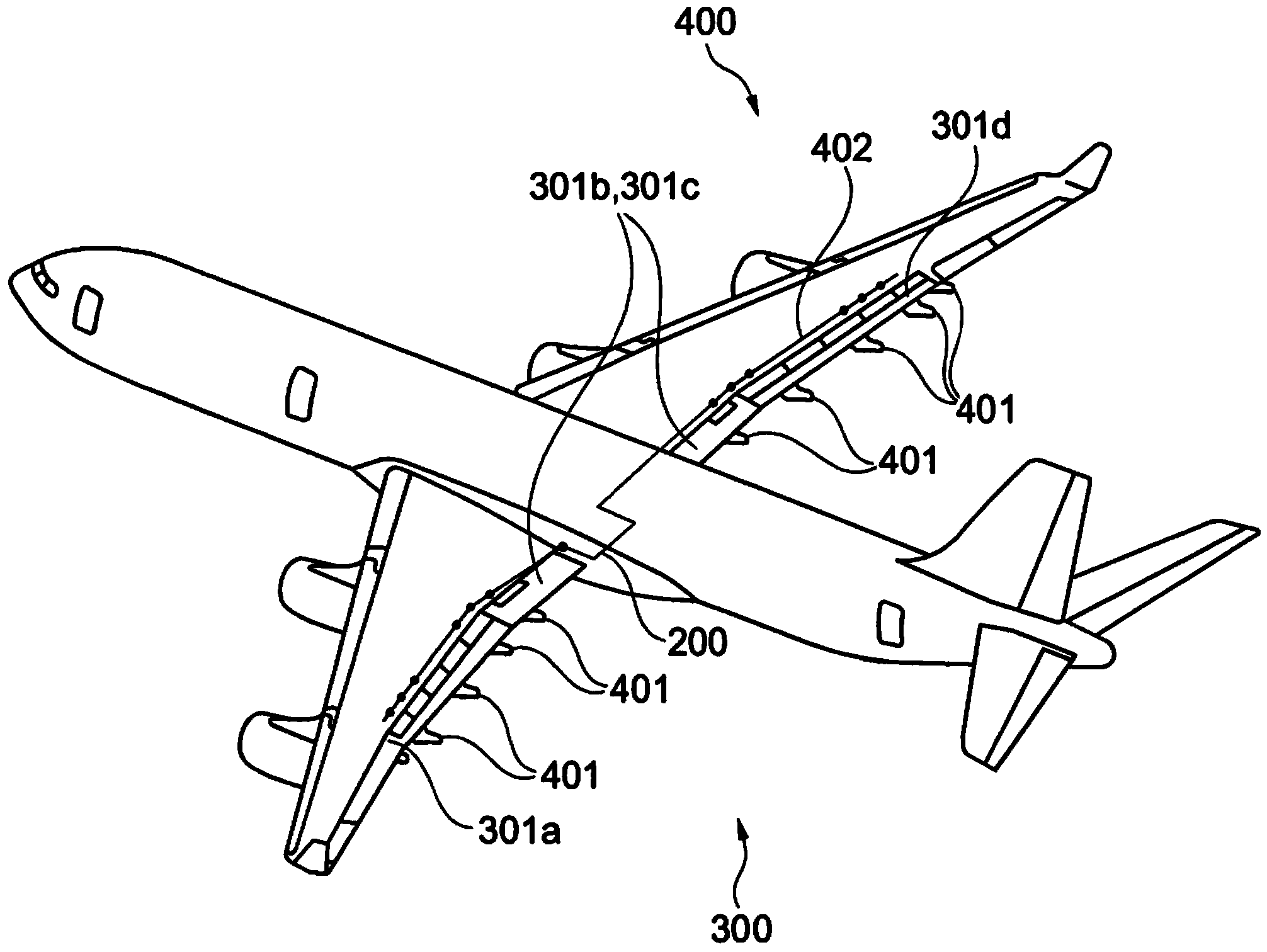
[0064] figure 1 Embodiments of the present invention are shown. figure 1 Shown is an all-electric, internally redundant drive 200 for use in a high-lift system for an aircraft according to the invention. The drive means comprise an electric motor 201a driving the landing flaps (not shown) of the high-lift system. In this context, the electric motor 201a is characterized by internal redundancy created by redundant wiring.

[0065] Internally redundant brakes 202 are also shown; it should be emphasized that only a single brake is required to lock the entire drive system. Also shown are the control electronics 203a actuating the phase groups of the individual sub-motors of the electric motor 201a. In context, for example in Figure 4 As shown in , each sub-motor can also be individually controlled by the corresponding control electronics.

[0066] Also shown is a shaft 206 to which the electric motor 201a transmits all of the torque. Also shown is a reduction gear unit 20...


PUM


Abstract

A high lift system for an aircraft, which extends and retracts the landing flaps of the aircraft in a fully electric manner. In this context, a fully electric drive is used, comprising an electric motor having an internal redundancy, in such a way that the electric motor is configured as a fault-tolerant electric motor. It may thus be possible to do without a coupling gear unit in the electric motor.

Description

[0001] References to related applications [0002] This application claims the benefit of the filing dates of German Patent Application No. 102011016336.0, filed April 7, 2011, and U.S. Provisional Patent Application No. 61 / 473,030, filed April 7, 2011, the disclosures of which are hereby incorporated by reference incorporated into this article. technical field [0003] The invention relates to driving a lift system in an aircraft. In particular, the invention relates to high-lift systems for aircraft, aircraft comprising high-lift systems, and the use of electric motors to drive high-lift systems. Background technique [0004] A conventional high lift system consists of leading edge flaps (slats) and trailing edge flaps (flaps) actuated via a power control unit (PCU). Such a power control unit usually consists of two hydraulic motors connected by a speed summing gear unit. Drive torque is transmitted to the individual drive stations via a propshaft system. Each drive st...

Claims


Application Information

Patent Timeline
Patent Type & Authority Applications(China)
IPC IPC(8): B64C13/24B64C13/50
CPCH02K3/28Y02T50/44B64C13/24B64C9/16B64C13/50B64C3/50B64C9/22B64C13/505Y02T50/40
Inventor 马库斯·克里斯特曼克里斯托夫·吉贝勒马丁·雷克西克比约恩·德尔
Owner AIRBUS OPERATIONS GMBH
Why Eureka
Try Eureka