Differential wet electric precipitator

A wet electrostatic precipitator, differential technology, applied in the direction of external electrostatic separator, electrode structure, electrostatic separation, etc., can solve the problems of late start, low utilization rate of flat electric field space, inability to effectively play the advantages of wet electrostatic precipitator, etc., to achieve The dust collection area is large, the electric field space utilization rate is high, and the effect of improving the dust collection efficiency

Active Publication Date: 2014-02-19
江苏力洁达环保设备工程有限公司
View PDF5 Cites 12 Cited by
  • Summary
  • Abstract
  • Description
  • Claims
  • Application Information

AI Technical Summary

Problems solved by technology

[0006] However, domestic wet electrostatic precipitators started relatively late, and most of the electric field structures of wet electrostatic precipitators currently used still use conventional flat electric fields, but the dust cleaning method is changed to water washing, which cannot effectively utilize the advantages of wet electrostatic precipitators.
Moreover, the wind speed selection of the electric field of large-scale units is relatively high, and the dust removal efficiency of the equipment is not high due to the low space utilization rate of the flat electric field

Method used


Image

  • Differential wet electric precipitator
  • Differential wet electric precipitator
  • Differential wet electric precipitator

Examples


Embodiment Construction

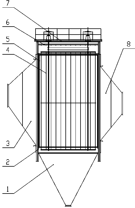
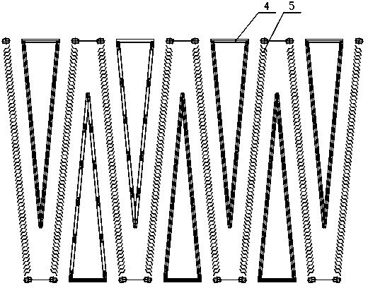
[0022] like figure 1 As shown, the ash hopper 1 is arranged at the lower part of the casing 2, the inlet head 3 and the outlet head 8 are arranged on both sides of the casing 2, and the top cover 7 is arranged on the top of the casing 2, thereby forming a sealed chamber. The cathode frame 4 and the differential plate row 5 are arranged in a staggered manner inside the housing 2 , and the cathode shower system 6 is arranged on the upper part of the cathode frame 4 with a certain distance from the cathode frame 4 .

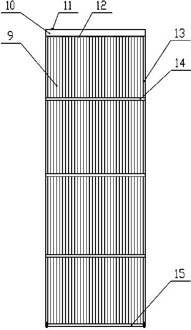
[0023] like figure 2 As shown, the differential plate row 5 is composed of a number of differential plates 9 arranged equidistantly. The upper part of the hanging beam 10 is correspondingly provided with a water inlet 11, and the lower part is provided with a first nozzle 12. The first nozzle 12 is arranged in the center between the differential plates 9. The first nozzle 12 adopts a two-way pointing type, which can be directed to the two sides respectively. The ...


PUM


Abstract

The invention discloses a differential wet electric precipitator which is applied to the field of atmospheric pollution abatement. Every two adjacent differential polar plate rows are arranged to form a certain angle, so a plurality of mutually wedging sphenoid spaces are formed; each cathode framework is located in one sphenoid space and has a shape matching with that of the sphenoid space, and two working surfaces are respectively parallel to planes of differential polar plate rows at two sides; each sphenoid space forms a large-opening section and a small-opening section at an electric field entry-exit section, wherein the small-opening section is blocked off by using a baffle plate. Compared with a common plate-type electric field wet electric precipitator, the differential wet electric precipitator provided by the invention has the following advantages: under the condition of a same space volume, the utilization rate of space of an electric field is high, a dust collecting area is great, and flue dust collection efficiency is improved; with a special electric field structure, a low flow velocity zone exists in the electric field, and collection efficiency of PM 0.1-10 dust and water spray is high; a continuous and uniform water film is formed on the surfaces of polar plates, so ash deposition on the polar plates never happens, thereby guaranteeing high-efficiency stable operation of equipment.

Description

technical field [0001] The invention relates to the technical field of dust removal equipment used for flue gas treatment, in particular to a differential wet electrostatic precipitator. Background technique [0002] In recent years, environmental pollution and ecological damage have become increasingly serious, and urban smog has also occurred frequently. For this reason, the country's implementation of air pollution emission standards has been continuously improved. At present, the country's smoke and dust emission standards for coal-fired, metallurgical and other industries are controlled at 20~30mg / Nm 3 . In the next few years, the country will further raise the standards for smoke and dust emissions, which will also put forward higher requirements for the performance and reliability of dust removal equipment. [0003] At present, most of the flue gas treatment process layout adopts the process route of pre-dust removal and post-desulfurization. When the original dust ...

Claims


Application Information

Patent Timeline
Patent Type & Authority Applications(China)
IPC IPC(8): B03C3/16B03C3/38B03C3/40B03C3/78
Inventor 江森广马玉初沈翠凤王建平江保祥陆涵军
Owner 江苏力洁达环保设备工程有限公司
Why Eureka
Try Eureka