
A heat dissipation control method for a loader engine

A control method and engine technology, which is applied in the direction of machine/engine, engine components, engine cooling, etc., can solve the problems of large changes in fan speed, affecting the service life of shafts, and large range of speed changes, so as to achieve good energy-saving effect and prolong The effect of service life and stable fan speed

Active Publication Date: 2017-01-04
GUANGXI LIUGONG MASCH CO LTD +1
View PDF2 Cites 0 Cited by
  • Summary
  • Abstract
  • Description
  • Claims
  • Application Information

AI Technical Summary

Problems solved by technology

Its disadvantages are: the temperature of the inlet and outlet of the heat dissipation component is used as the control parameter. Since the engine speed of the loader changes in a large range when it is working, it is easy to cause the change of the throttle, resulting in a large change in the speed of the fan, which produces a lot of noise; The fan shaft is repeatedly impacted, which affects the service life of the shaft
Its disadvantages are: the temperature of the engine coolant is used as the control parameter. Since the engine speed of the loader varies in a large range during operation, it is easy to cause changes in the throttle, resulting in a large change in the speed of the fan, resulting in loud noise; at the same time, the fan shaft is repeatedly adjusted. Shock, which affects the service life of the shaft

Method used


Image

  • A heat dissipation control method for a loader engine

Examples


Embodiment 1

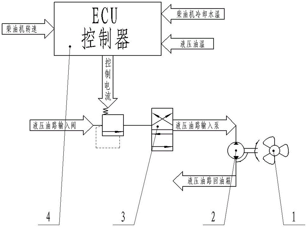
[0025] Such as figure 1 As shown, the present invention includes a fan 1 and a hydraulic motor 2 for driving the fan 1, the hydraulic motor 2 is connected with the electric proportional pressure reducing valve 3, the electric proportional pressure reducing valve 3 is connected with the ECU controller 4, and the ECU controller 4 is provided with a receiver The engine speed signal unit, the unit is connected with the engine speed measuring instrument, the engine speed change rate δ every 30ms≤45rpm, the ECU controller 4 takes water temperature and oil temperature as control parameters, slowly adjusts the current of the electric proportional pressure reducing valve 3, and controls the drive The hydraulic motor 2 of the fan 1 makes the whole machine work in the optimum temperature range.

[0026] In this embodiment, because the engine speed change rate δ is less than or equal to 45 rpm per 30 ms, the ECU controller 4 uses water temperature and oil temperature as control parameters...

Embodiment 2

[0028] The difference from Embodiment 1 is that the ECU controller 4 only takes the engine speed as the control parameter to control the speed of the fan when the engine speed change rate δ is greater than 45rpm every 30ms, adjusts the current of the electric proportional pressure reducing valve 3, and controls the driving fan The hydraulic motor 2 of 1 makes the fan 1 work stably within a certain speed range or makes the fan 1 speed change slowly.

[0029] In this embodiment, because the rate of change of the engine speed δ is greater than 45rpm every 30ms, the ECU controller 4 only uses the engine speed as a control parameter to adjust the current of the electric proportional pressure reducing valve 3 to control the hydraulic motor 2 driving the fan 1, so that the fan 1 The speed changes slowly to achieve the effect of energy saving and noise reduction.


PUM


Abstract

The invention discloses a heat dissipation control method for an engine of a loading machine, and provides a method for controlling a heat dissipation system of a loading machine. By using the method, the revolving speed of a fan is changed smoothly, the noise of the fan is low, the service life of the heat dissipation system is long, the energy-saving effect of the heat dissipation system is high, and the cost of the heat dissipation system is low. The heat dissipation system comprises the fan and a hydraulic motor for driving the fan, the hydraulic motor is connected with an electric proportional pressure reducing valve, and the electric proportional pressure reducing valve is connected with an ECU (electronic control unit). The heat dissipation control method for the engine of the loading machine is characterized in that when the revolving speed variation delta of the engine is smaller than or equal to 45rpm per 30ms, water temperature and oil temperature serve as control parameters of the ECU, and the whole engine is ensured to work in the optimized temperature range; and when the revolving speed variation delta of the engine is greater than 45rpm per 30ms, only the revolving speed of the engine serves as the control parameter of the ECU, the current of the electric proportional pressure reducing valve is quickly adjusted according to an arithmetic, and the hydraulic motor which drives the fan guarantees that the fan stably works in a certain revolving range or the revolving speed of the fan is changed slowly. The heat dissipation control method for the engine of the loading machine is applicable to a situation that the changing range of the revolving speed of the engine is wide, and the revolving speed of the engine is changed quickly.

Description

technical field [0001] The invention relates to the field of engine heat dissipation control, in particular to a heat dissipation control method for a loader engine. Background technique [0002] The loader is mainly used for shoveling, loading, unloading, transporting bulk materials such as soil and stone, and can also perform light shoveling operations on rocks and hard soil. If you change to a different working device, it can also complete the work of bulldozing, lifting, loading and unloading other materials. In highway construction, it is mainly used for filling and excavation of roadbed engineering, aggregate and loading of asphalt and cement concrete yards. Because it has the advantages of fast operating speed, good maneuverability, and light operation, it has developed rapidly and has become the main machine in earth-rock construction. [0003] At present, there are two types of heat dissipation for loader engines: direct-coupled and hydraulically driven fans: the ...

Claims


Application Information

Patent Timeline
Patent Type & Authority Patents(China)
IPC IPC(8): F01P7/04F04D27/00F04D29/66
Inventor 孙金泉蔡登胜金忠陶林裕
Owner GUANGXI LIUGONG MASCH CO LTD
Learn More