Magnetorheological Pressure Control Valve

A pressure control and magneto-rheological technology, applied in the field of pressure control valves, can solve the problems that it is difficult to achieve rapid pressure, stepless changes, high requirements on the valve core spring, and small valve core movement, so as to achieve high energy utilization efficiency, Small value change, good heat dissipation effect

Active Publication Date: 2015-11-25
浙江孔辉汽车科技有限公司
View PDF4 Cites 2 Cited by
  • Summary
  • Abstract
  • Description
  • Claims
  • Application Information

AI Technical Summary

Problems solved by technology

In the traditional design, the machining accuracy is high, and the product consistency is poor; the requirements for the valve core spring are very high, and it is not easy to achieve rapid and stepless pressure changes; the valve core movement is generally small; the power consumption is very low. Large, not very energy efficient

Method used


Image

  • Magnetorheological Pressure Control Valve
  • Magnetorheological Pressure Control Valve
  • Magnetorheological Pressure Control Valve

Examples


Embodiment Construction

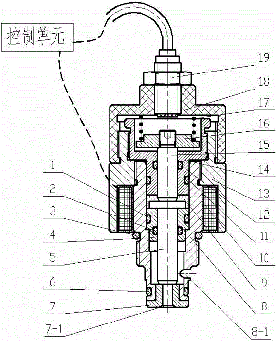
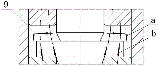
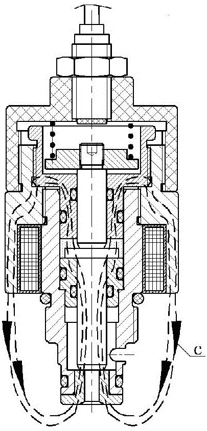
[0015] attached by figure 1 As shown: the magnetorheological pressure control valve includes: inner valve body 4, valve core 5, plug cover 7, main valve body 8, working chamber 9 (with magnetorheological fluid inside), coil assembly 10 (including coil and isolation Magnetic jacket), outer valve body 13, upper valve body 14, thrust shaft 15, spring seat 16, return spring 17, end cover 18, travel switch sensor 19 and multiple rubber sealing rings (1, 2, 3, 6, 11 , 12). The travel switch sensor 19 and the end cap 18 are threadedly connected to the upper end of the end cap 18, and the end cap 18 is an insulating material; The valve body 14 is threadedly connected to the upper and outer sides of the upper valve body 14, the upper valve body 14 is arranged on the inner side of the main valve body 8 and is provided with a rubber sealing ring 11 between the main valve body 8, the outer valve body 13 and the upper valve body 14 All are magnetically conductive materials; the bottom of...


PUM


Abstract

The invention relates to a pressure control valve, in particular to a magnetorheological pressure control valve for achieving hydraulic system pressure control through a force required to start the control valve. The pressure control valve comprises an inner valve body, a valve core, a blanking cap, a main valve body, a working chamber containing magnetorheological fluid, a coil assembly composed of a coil and a magnet separation jacket, an outer valve body, an upper valve body, a thrust shaft, a spring seat, a reset spring, an end cap, a travel switch sensor and a plurality of rubber seal rings. The magnetorheological pressure control valve is simple in structure, convenient to manufacture, high in energy efficiency and quick in pressure response and stepless and intelligent control of system pressure can be achieved.

Description

technical field [0001] The invention relates to a pressure control valve, in particular to a magneto-rheological pressure control valve which realizes pressure control of a hydraulic system by controlling the force required when the valve is opened. Background technique [0002] Common pressure control valves usually control the system pressure by controlling the preload of the spool spring. Traditional pressure control valves control the pre-tightening force of the control spool spring by changing the magnetic field of the electromagnetic coil, thereby changing the force required for the spool to open, and then controlling the system pressure. In the traditional design, the machining accuracy is high, and the product consistency is poor; the requirements for the valve core spring are very high, and it is not easy to realize the rapid and stepless pressure change; the valve core movement is generally small; the power consumption is very low. Large and not energy efficient. ...

Claims


Application Information

Patent Timeline
Patent Type & Authority Patents(China)
IPC IPC(8): F16K31/06F16F9/34
CPCF16F9/34F16K31/06F16K31/12
Inventor 郭孔辉刘洋章新杰
Owner 浙江孔辉汽车科技有限公司
Why Eureka
Try Eureka