Gas turbine fuel oil metering method based on electric pump

A technology for gas turbines and metering methods, which is applied in the direction of volume/mass flow generated by mechanical effects, fixed measuring chambers, and fluid flow detection by measuring differential pressure, which can solve the problems of reliability, cost, and metering accuracy.

Active Publication Date: 2014-02-19
AECC SHENYANG ENGINE RES INST
View PDF4 Cites 5 Cited by
  • Summary
  • Abstract
  • Description
  • Claims
  • Application Information

AI Technical Summary

Problems solved by technology

[0014] The purpose of the present invention is to solve the problem that the reliability, cost and measurement accuracy of the existing g

Method used


Image

  • Gas turbine fuel oil metering method based on electric pump
  • Gas turbine fuel oil metering method based on electric pump
  • Gas turbine fuel oil metering method based on electric pump

Examples


Embodiment 1

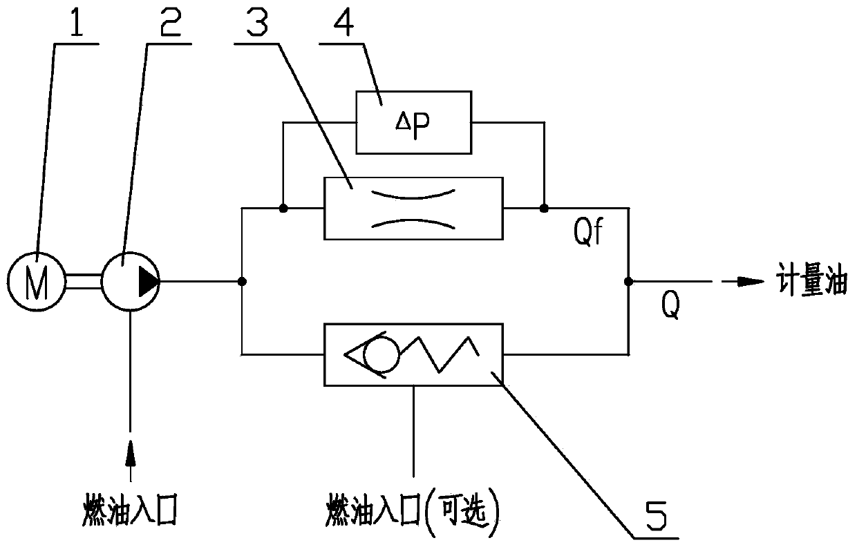
[0036] This embodiment provides a gas turbine fuel metering method based on an electric pump, characterized in that: the electric pump-based gas turbine fuel metering method includes the following steps;

[0037] 1) The displacement fuel pump is driven by a speed-regulating motor to change the fuel flow;

[0038] 2) Parallel throttling device and pressure limiting device at the outlet of positive displacement pump;

[0039] 3) Use a differential pressure measuring device to measure the pressure difference between the inlet and outlet of the throttling device;

[0040] 4) Properly set the opening pressure of the pressure limiting device so that the device is closed during the start-up of the gas turbine and opened after start-up;

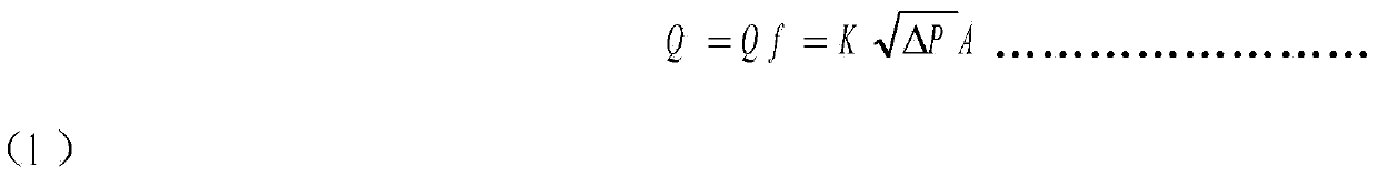
[0041] 5) During the starting process, the pressure limiting device is closed, and the fuel flow is accurately calculated using the flow area of ​​the throttling device and the pressure difference between the inlet and outlet;

[0042] 6) After sta...

Embodiment 2

[0053] This embodiment provides a gas turbine fuel metering method based on an electric pump, characterized in that: the electric pump-based gas turbine fuel metering method includes the following steps;

[0054] 1) The displacement fuel pump is driven by a speed regulating motor to change the fuel flow;

[0055] 2) Parallel throttling device and pressure limiting device at the outlet of positive displacement pump;

[0056] 3) Use a differential pressure measuring device to measure the pressure difference between the inlet and outlet of the throttling device;

[0057] 4) Properly set the opening pressure of the pressure limiting device so that the device is closed during the start-up of the gas turbine and opened after start-up;

[0058] 5) During the starting process, the pressure limiting device is closed, and the fuel flow is accurately calculated by using the flow area of ​​the throttling device and the pressure difference between the inlet and outlet;

[0059] 6) After ...


PUM


Abstract

A gas turbine fuel oil metering method based on an electric pump comprises the following steps that a positive displacement pump is driven by an adjustable-speed motor to change the flow of fuel oil; an outlet of the positive displacement pump is connected with a throttling device and a pressure limiting device in parallel; a differential pressure measuring device is used for measuring the pressure difference of an inlet and an outlet of the throttling device; the opening pressure of the pressure limiting device is properly set, and the pressure limiting device is made to be closed in the gas turbine starting process and is opened after a gas turbine is started; in the starting process, the pressure limiting device is closed, and the flow of the fuel oil is precisely calculated through the flow area of the throttling device and the pressure difference of the inlet and the outlet of the throttling device; after the gas turbine is started, the pressure limiting device is opened, the rotating speed of the adjustable-speed motor is adjusted, and the flow of the fuel oil is metered in a common electric pump mode. The gas turbine fuel oil metering method has the advantages of being capable of being directly applied to a gas turbine fuel oil system and capable of being applied to a combustion chamber, a turbine and other component test equipment of the gas turbine. Reliability, cost and metering accuracy can be considered in the system, and the overall performance of the fuel oil system and even the gas turbine can be obviously improved.

Description

technical field [0001] The invention relates to the technical field of gas turbine fuel system, in particular to a gas turbine fuel metering method based on an electric pump. Background technique [0002] The gas turbine performs external work by burning fuel oil. The main function of the fuel system is to measure the fuel flow to the combustion chamber of the gas turbine to realize the state control of the gas turbine. Gas turbines have different requirements for fuel metering performance under different working conditions, which can usually be divided into two stages: "starting process" and "after starting". The fuel flow required for the "starting process" is small, and accurate metering of the fuel is required to ensure reliable starting; the fuel flow required for the "after starting" is large, but the closed-loop control of the speed can be entered after the start is successful, that is, the gas turbine is driven by increasing or decreasing the fuel. The speed is cons...

Claims


Application Information

Patent Timeline
IPC IPC(8): G01F1/36G01F11/28
Inventor 左伟金鑫李军
Owner AECC SHENYANG ENGINE RES INST
Why Eureka
Try Eureka