Electromagnetic loading device for concrete durability test

A durability test and loading device technology, applied in the field of cement and concrete basic research, can solve the problems of spring effective area reduction, loading device failure, stress relaxation, etc., to avoid stress changes, simple force application method, and small occupied volume Effect

Inactive Publication Date: 2014-02-19
NANJING UNIV OF TECH
View PDF5 Cites 5 Cited by
  • Summary
  • Abstract
  • Description
  • Claims
  • Application Information

AI Technical Summary

Problems solved by technology

The principle of the device is simple, the volume is small, and it is suitable for the existing standard carbonization box and other durable instruments. It can realize the multi-factor coupling of stress and environment, and can load three test blocks at the same time, which greatly improves the efficiency; its disadvantage is that : ① Use the sampled spring elastic coefficient as the elastic coefficient of all springs. A small change in the spring coefficient will cause a large load change, so that the force exerted by the spring device has a large deviation on the individual, resulting in the inability to carry out accurate loading; ② Spring There is a problem of stress relaxation in the loading device during the long-term loading process; ③ In the concrete durability test under the coupling effect of load and corrosive environment, the spring loading device is affected by corrosion, and the effective area of ​​the spring is continuously reduced, resulting in the failure of the loading device
[0005] The above-mentioned shortcomings severely limit the wide application of bending-tensile stress loading devices in multi-factor durability tests of concrete.

Method used


Image

  • Electromagnetic loading device for concrete durability test
  • Electromagnetic loading device for concrete durability test

Examples


Embodiment Construction

[0023] The present invention will be further described below in conjunction with the accompanying drawings and specific embodiments.

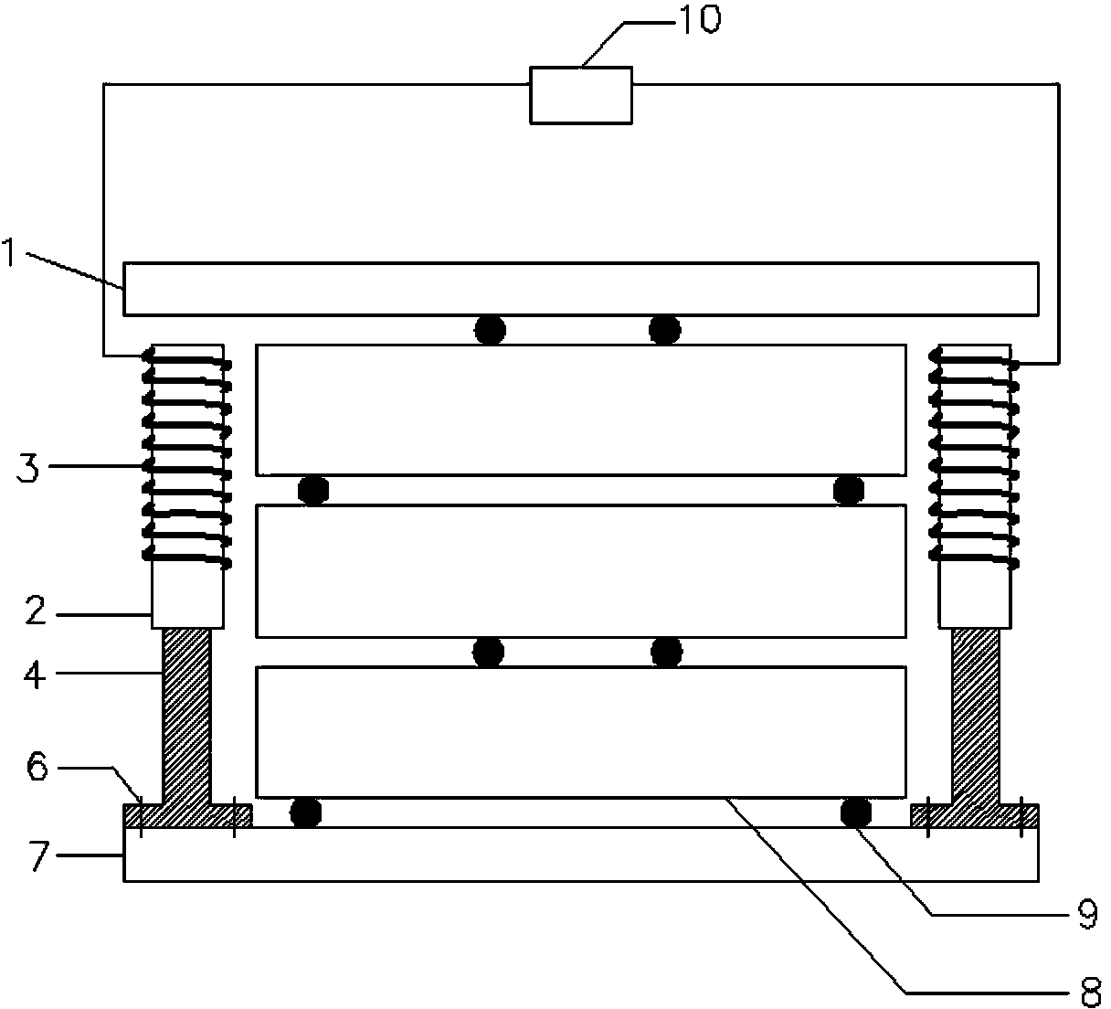
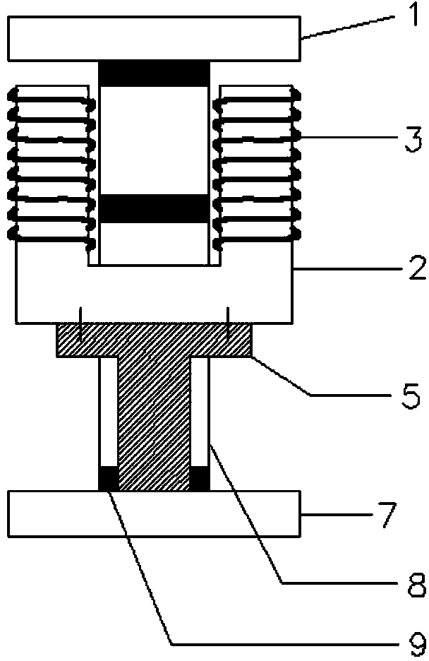
[0024] Such as figure 1 with figure 2 As shown, the core component of the electromagnetic loading device is an electromagnet device, and the electromagnet is composed of an upper platen 1 , a DC coil 3 , an iron core 2 , and an iron core support 4 . Wherein, the upper pressing plate 1 plays the role of the armature in the electromagnet, and the upper pressing plate 1 is made of steel plate. The iron core 4 is made of iron core laminations and a stainless steel iron core shell. The iron core lamination is made of U-shaped silicon steel sheets bent at 90 degrees, and the rigidity is small. In order to increase the overall rigidity of the electromagnet and prevent corrosion, a stainless steel core shell is wrapped around the iron core lamination. The iron core casing is a welded structure, fixed with the iron core laminations by bolts, and the...


PUM


Abstract

The invention discloses an electromagnetic loading device for a concrete durability test. The electromagnetic loading device comprises an upper pressing plate, direct-current coils, two iron cores, iron core brackets, upper bolts, lower bolts, a lower pressing plate, concrete test pieces, cushion rods and a direct-current power supply, wherein the concrete test piece is arranged between the upper pressing plate and the lower pressing plate; the cushion rods are arranged between the upper pressing plate and each concrete test piece, between the concrete test pieces and between the concrete test piece and the lower pressing plate; the iron core brackets are arranged on the two sides of the concrete test piece respectively; the lower parts of the iron core brackets are fixed to the lower pressing plate through the lower bolts; the upper parts of the iron core brackets are connected with the iron cores through the upper bolts; the two iron cores are wound with the direct-current coils respectively; the direct-current coils are connected with the direct-current power supply. The electromagnetic loading device is suitable for the durability test of a concrete material under the coupling effect of load and corrosion environment factors, and can be used for achieving accurate load application and keeping non stress relaxation in a long-term loading process.

Description

technical field [0001] The invention belongs to the field of basic research on cement and concrete, and relates to a loading device utilizing the electromagnetic principle, in particular to an electromagnetic loading device used for concrete durability tests. Background technique [0002] In recent years, due to insufficient durability of concrete structures, the accidents of premature failure and shortened life of concrete structures have been increasing, especially the accidents of major projects such as dams, roads, bridges, ports, and high-rise buildings that have not reached the design period. Occurs from time to time, causing huge economic losses and casualties. Although the research on the durability of concrete has been done for decades, most of the research work considers the durability under the action of a single environmental damage factor; however, in fact, the durability of actual engineering concrete should operate under the joint action of stress and differen...

Claims


Application Information

Patent Timeline
Patent Type & Authority Applications(China)
IPC IPC(8): G01N3/02
Inventor 韩建德梁羽刘伟庆王曙光徐锋
Owner NANJING UNIV OF TECH
Why Eureka
Try Eureka