Carbon nanotube sensor and production method

A technology of carbon nanotubes and sensors, applied in the field of sensors, can solve the problems of complex quantitative relationship, inability to align, low measurement efficiency, etc., and achieve the effect of simple quantitative relationship

Inactive Publication Date: 2014-02-19
BEIJING NORMAL UNIVERSITY
View PDF4 Cites 3 Cited by
  • Summary
  • Abstract
  • Description
  • Claims
  • Application Information

AI Technical Summary

Problems solved by technology

Due to the Schottky barrier, the contact resistance is very large, which is very unfavorable for the accurate measurement of the change in the conductivity of the test paper caused by the combination of antigen-antibody, and will deteriorate the signal-to-noise ratio and dynamic range of the measurement.
Traditional extraction electrodes need to deposit metal and process high-temperature alloys at hundreds of degrees Celsius, while paper substrates cannot withstand such high-temperature treatment
[0008] (2) Each test strip can only use one probe substance to detect one target substance at a time, and cannot simultaneously detect multiple target substances, and the measurement efficiency is low
[0009] (3) The sensitive area of ​​the carbon nanotube sensor is prepared by the dip coating method, and the sensitive area array or continuous, circuitous curve shape cannot be made, and the width of the test strip cannot be made very narrow, and the detection sensitivity is limited.
[0010] (4) The carbon nanotubes are in an uncontrollable disordered distribution state on the test paper, and cannot be oriented in a specific direction, which is inconvenient to optimize the influence of the specific combination or reaction of the probe substance-target substance on its conductivity characteristics
In other words, there is a complex series-parallel mixing relationship between the micro-regions where the conductance changes and the region where the conductance does not change. The quantitative relationship between the content of the target substance and the total resistance of the test paper is very complicated, resulting in a low resolution for the quantitative analysis of the target substance. , the dynamic range is limited

Method used


Image

  • Carbon nanotube sensor and production method
  • Carbon nanotube sensor and production method
  • Carbon nanotube sensor and production method

Examples


Embodiment 1

[0050] This embodiment provides a carbon nanotube sensor to more accurately measure the change in the conductivity of the sensitive area, so that the carbon nanotube sensor can be used to achieve detection more accurately.

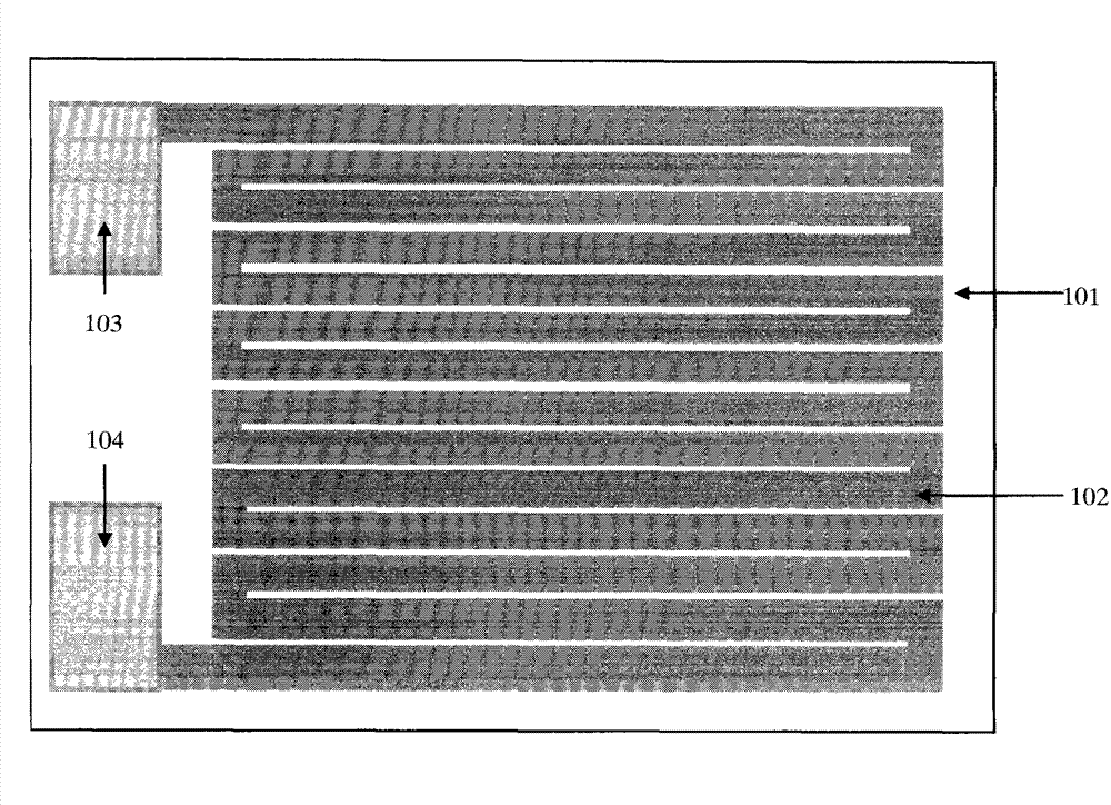
[0051] figure 1 A structural diagram of a carbon nanotube sensor according to Embodiment 1 of the present invention is shown. like figure 1 As shown, the carbon nanotube sensor includes: a substrate 101 and a sensing unit located on the substrate.

[0052] In this embodiment, the substrate 101 may be one of filter paper, printing paper, and polyethylene terephthalate, but the present invention is not limited thereto, but may be suitable for providing support for the sensing unit and not Any sheet material that conducts electricity, for example, the substrate can also be cloth, printed circuit board, ceramics, silicon wafer covered with silicon dioxide film, glass, etc.

[0053] The sensing unit includes a sensitive area 102 and a first electrode 103 and...

Embodiment 2

[0074]Described in Example 1 is the case where a sensing unit is formed on a substrate. In this case, a sensor can only use one probe substance to detect one target substance at a time, and cannot detect multiple target substances simultaneously. In order to further solve this problem, in this embodiment, two or more sensor units are formed on the substrate. The plurality of sensing units can be arranged in parallel to form an array. Each sensing unit may have the same structure as the sensing unit in Example 1, and the probe substances in the sensitive regions of different sensing units may be different.

[0075] Figure 4 and Figure 5 A schematic diagram showing a carbon nanotube array with different patterns of sensitive region arrays formed on a substrate. exist Figure 4 and Figure 5 Among them, each sensitive area 402, 502 of the sensitive area array contains different probe substances and carbon nanotubes. in formation Figure 4 and Figure 5 When the array o...

Embodiment 3

[0079] This embodiment provides another carbon nanotube sensor to more accurately measure the change in the conductivity of the sensitive area, so that the carbon nanotube sensor can be used to achieve detection more accurately.

[0080] The carbon nanotube sensor in this embodiment has the same figure 1 similar structure, so will still refer to figure 1 to describe. like figure 1 As shown, the carbon nanotube sensor includes: a substrate 101 and a sensing unit located on the substrate.

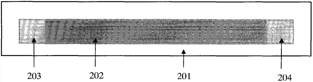
[0081] The sensing unit includes a sensitive area 102 and a first electrode 103 and a second electrode 104 connected to two ends of the sensitive area. The sensitive zone consists of carbon nanotubes mixed with probe species.

[0082] In this embodiment, in order to solve the complex series-parallel mixing relationship between the micro-regions with changed conductance and the regions with no change in conductance due to the large-area continuous distribution of carbon nanotubes in the se...


PUM

PropertyMeasurementUnit
widthaaaaaaaaaa
widthaaaaaaaaaa
diameteraaaaaaaaaa

Abstract

The invention relates to a carbon nanotube sensor and a production method. The carbon nanotube sensor comprises a substrate and at least one sensor unit arranged on the substrate. Each sensor unit comprises a sensitive zone which is composed of carbon nanotubes of mixed probe substances, and a first electrode and a second electrode which are connected with two end parts of the sensitive zone. The first electrode and the second electrode form ohmic contact with the carbon nanotubes. The carbon nanotube sensor can detect change of conductivity of the sensitive zone accurately, and therefore the carbon nanotube sensor can be used for detection accurately.

Description

technical field [0001] The invention relates to the field of sensors, in particular to the detection of tiny and trace organisms and chemical substances. The invention can be used for early diagnosis of cancer in the medical field, detection of body indicators, environmental monitoring, monitoring of biochemical substances in the field of anti-terrorism, and the like. Background technique [0002] In biomolecular detection, the detection of cancer markers is an important part. The earlier cancer is found, the better the chances of being cured. Existing common cancer diagnosis techniques, such as endoscopy and CT scanning, are costly and inaccurate, and often cannot accurately diagnose cancer in its early stages. Therefore, how to diagnose cancer earlier, more accurately, more conveniently and at low cost has attracted the attention of many researchers. [0003] In recent years, carbon nanotubes have been widely used to make electrochemical sensors for detecting biomacromo...

Claims


Application Information

Patent Timeline
Patent Type & Authority Applications(China)
IPC IPC(8): G01N27/26
Inventor 韩德俊陈文飞
Owner BEIJING NORMAL UNIVERSITY
Why Eureka
Try Eureka