
Low back chamber ultra wide band resistor loading dipole antenna

A dipole antenna and ultra-wideband technology, which is applied in the field of low-back cavity ultra-wideband resistively loaded dipole antennas, can solve the problems affecting crossing obstacles, etc., and achieve the effect of good time domain characteristics and low height

Active Publication Date: 2014-02-19
INST OF ELECTRONICS CHINESE ACAD OF SCI
View PDF1 Cites 4 Cited by
  • Summary
  • Abstract
  • Description
  • Claims
  • Application Information

AI Technical Summary

Problems solved by technology

The ultra-wideband antennas currently used all have a relatively high height. For example, the back cavity height of the resistance-loaded butterfly antenna with a center frequency of 500MHz is 15cm. After being installed at the bottom of the vehicle, it will seriously affect the ability of the vehicle to cross obstacles during the movement process.

Method used


Image

  • Low back chamber ultra wide band resistor loading dipole antenna
  • Low back chamber ultra wide band resistor loading dipole antenna
  • Low back chamber ultra wide band resistor loading dipole antenna

Examples


Embodiment Construction

[0015] In order to make the object, technical solution and advantages of the present invention clearer, the present invention will be described in further detail below in conjunction with specific embodiments and with reference to the accompanying drawings.

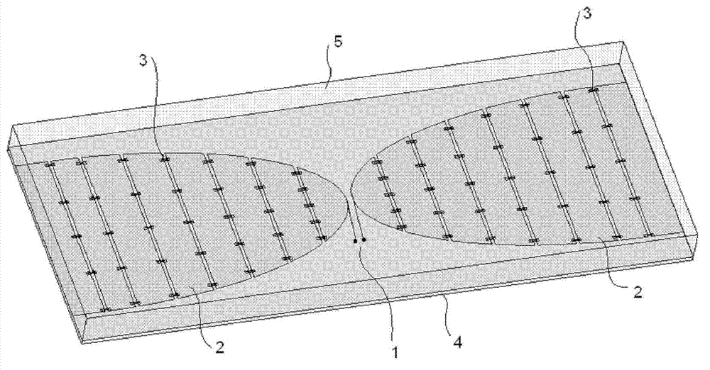
[0016] figure 1 It is a three-dimensional schematic diagram of a low-back cavity ultra-broadband resistance-loaded dipole antenna according to an embodiment of the present invention, such as figure 1 As shown, the low-back cavity ultra-broadband resistance-loaded dipole antenna includes: two radiating arms 2, a dielectric plate 4, an input port 1 and a metal back cavity 5, wherein:

[0017] Each of the two radiating arms 2 is semi-elliptical, and consists of a plurality of segmented metal strips and metal strips arranged in parallel and electrically connected (such as welded) to the radiating arms 2. The loading resistance 3 is composed of several parallel-connected loading resistors; the loading resistor 3 is welded bet...


PUM

PropertyMeasurementUnit
Long axisaaaaaaaaaa
Short axisaaaaaaaaaa
Lengthaaaaaaaaaa

Abstract

The invention discloses a low back chamber ultra wide band resistor loading dipole antenna. The antenna comprises two radiation arms, a medium board, an input port and a metal back chamber, wherein the two radiation arms are both half elliptic structures, each radiation arm comprises multiple segmented metal strips which are arranged parallelly and are electrically connected with the radiation arms and multiple loading resistors which are connected in parallel among the metal strips, the loading resistors are welding among every two adjacent metal strips of the radiation arms and are used for reducing reflected current of the radiation arms, the two radiation arms are symmetrically bonded at a right front surface of the medium board, opposite sides of the radiation arms are respectively provided with one input port, the input ports are taken as antenna feed ends and are for signal input, the metal back chamber is arranged above the radiation arms, and four edges of the metal back chamber are fixed together with four edges of the medium board. The low back chamber ultra wide band resistor loading dipole antenna has properties of simple structure and low profile, is suitable for being mounted at a bottom portion of a vehicle and does not influence travelling capability of the vehicle.

Description

technical field [0001] The invention relates to an antenna used in the field of ultra-wideband imaging radar, in particular to a low-back cavity ultra-wideband resistance-loaded dipole antenna. Background technique [0002] UWB antenna is a crucial part of UWB imaging radar system, which directly affects the performance of the whole system. Ultra-wideband imaging radar systems generally use ultra-wideband narrow pulse signals, so the antenna should have good radiation characteristics and broadband characteristics, as well as good time-domain characteristics. At present, the antennas commonly used in UWB imaging radars include resistor-loaded bow-tie antennas, TEM horn antennas, and helical antennas. In the vehicle ultra-wideband imaging radar system, the antenna is generally installed at the bottom of the vehicle body to improve the detection performance of the radar. Currently used ultra-wideband antennas have a relatively high height. For example, a resistor-loaded butte...

Claims


Application Information

Patent Timeline
IPC IPC(8): H01Q1/38H01Q21/00H01Q23/00
Inventor 纪奕才方广有卢伟周斌
Owner INST OF ELECTRONICS CHINESE ACAD OF SCI
Learn More