Energy system of micro-grid

An energy system and micro-grid technology, applied in the field of micro-grid, can solve the problems of failure to achieve low-carbonization goals, poor flexibility and reliability, etc., and achieve the effect of improving flexibility and reliability, improving quality, and realizing low-carbonization

Active Publication Date: 2014-02-19
SHANGHAI MUNICIPAL ELECTRIC POWER CO +1
View PDF4 Cites 29 Cited by
  • Summary
  • Abstract
  • Description
  • Claims
  • Application Information

AI Technical Summary

Problems solved by technology

It is used to solve the problems of poor flexibility and reliability of the energy s

Method used


Image

  • Energy system of micro-grid
  • Energy system of micro-grid
  • Energy system of micro-grid

Examples


Embodiment Construction

[0026] The present invention will be described in further detail below in conjunction with the accompanying drawings.

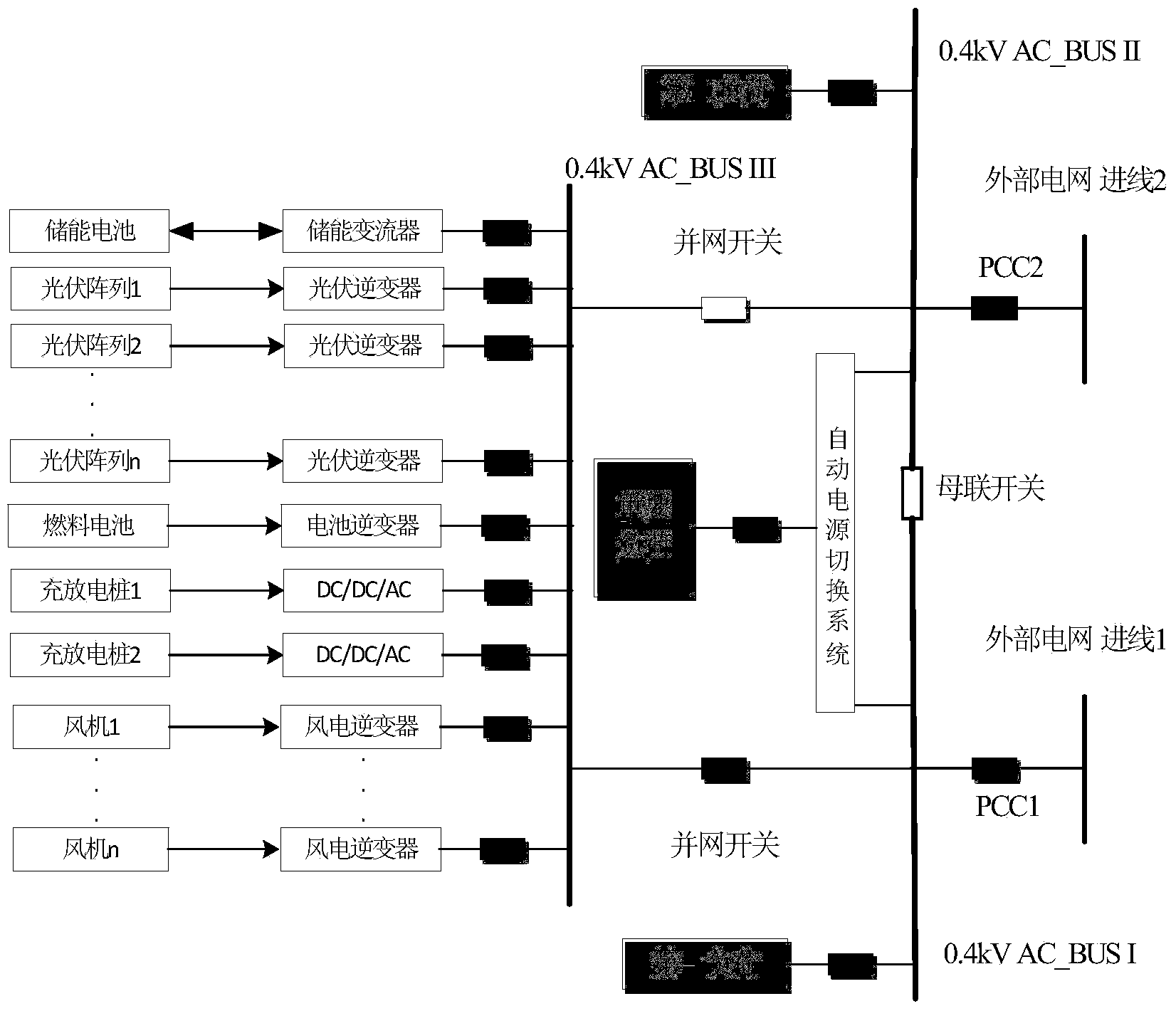
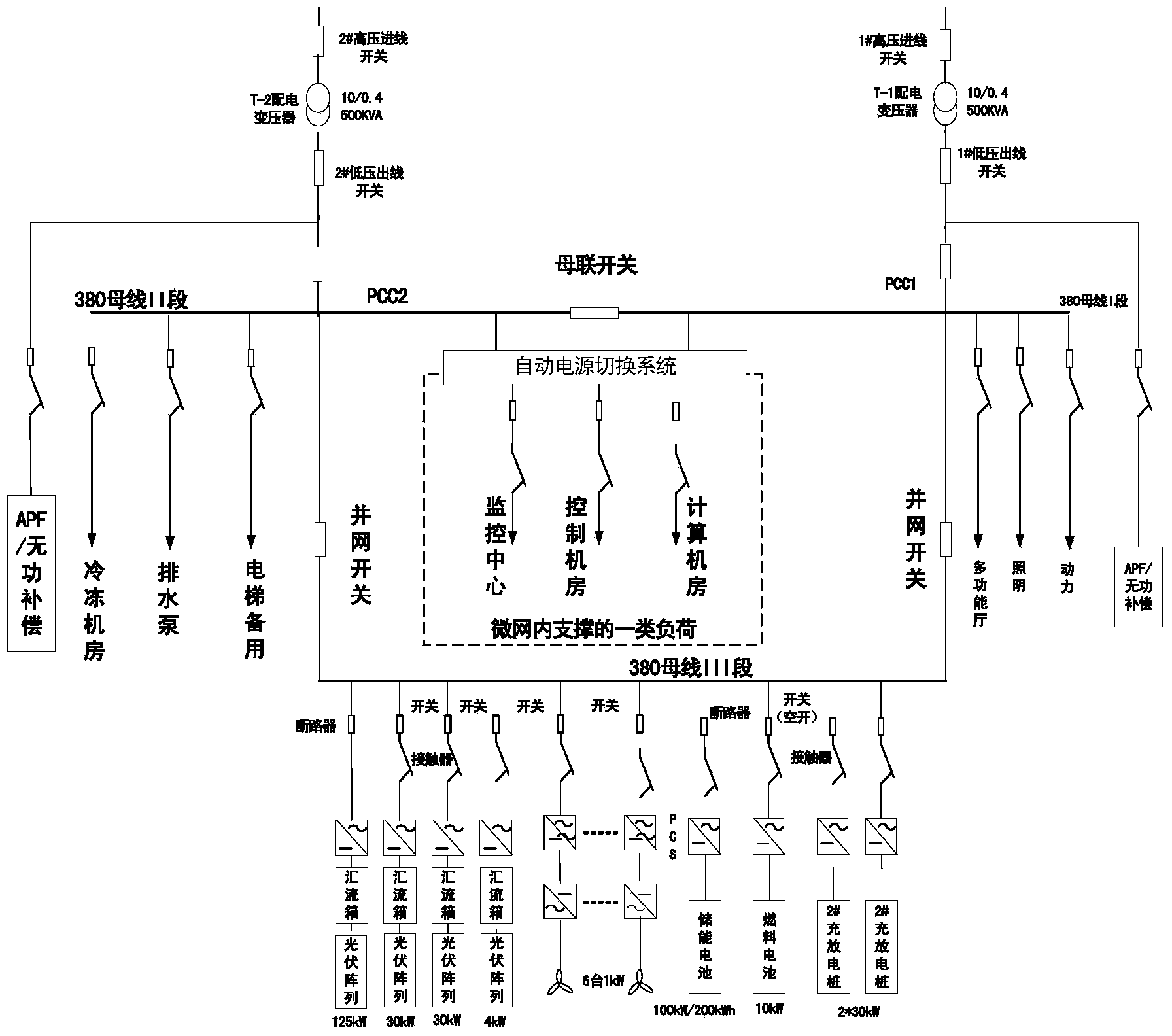
[0027] Such as figure 1 , the micro-grid energy system of the present invention includes a first busbar and a second busbar, the first busbar is connected to the first incoming terminal of the grid through a first static switch, and the second busbar is connected to the second incoming terminal of the grid through a second static switch , both the first bus and the second bus are connected with a load, a bus tie switch is connected between the first bus and the second bus, a third bus is set, and the two ends of the third bus are respectively connected through the first grid-connected The switch and the second grid-connected switch are respectively connected to the first busbar and the second busbar of the microgrid, and the third busbar is connected to the energy equipment of the microgrid, and the energy equipment of the microgrid includes a photovoltaic po...


PUM


Abstract

The invention relates to an energy system of a micro-grid. The energy system of the micro-grid comprises a first bus, a second bus and a third bus, wherein the first bus is connected with a first bus inlet end of a power grid through a first static switch, the second bus is connected with a second bus inlet end of the power grid through a second static switch, loads are connected to the first bus and the second bus respectively, a bus coupler switch is arranged between the first bus and the second bus in a connected mode, the two ends of the third bus are correspondingly connected with the first bus and the second bus of the micro-grid through a first grid-connecting switch and a second grid-connecting switch respectively, the third bus is connected with a micro-grid energy device, the micro-grid energy device comprises a photovoltaic power generation module, a wind power module, an energy storage module, a fuel cell module and a V2G module, a diverter switch is arranged between the photovoltaic power generation module and the third bus in a connected mode, a diverter switch is arranged between the wind power module and the third bus in a connected mode, a diverter switch is arranged between the energy storage module and the third bus in a connected mode, a diverter switch is arranged between the fuel cell module and the third bus in a connected mode, and a diverter switch is arranged between the V2G module and the third bus in a connected mode. The problems that flexibility and reliability of an energy system of an existing micro-grid are poor, and the low-carbon purpose is not achieved are solved.

Description

technical field [0001] The invention relates to the technical field of micro-grids, in particular to a micro-grid energy system. Background technique [0002] Distributed power generation technology has attracted widespread attention from the whole society due to its advantages of improving system power supply reliability, reducing end-user costs, reducing line loss, and improving power quality. Distributed power generation mainly includes various types of renewable energy power generation (wind energy, solar energy, biomass energy, etc.), and its clean and environmentally friendly features meet the requirements of low-carbon economic development. [0003] However, the connection of independent distributed generation to the grid has brought certain impacts on the grid due to its own intermittent, fluctuating, and random characteristics, which not only makes the power flow and fault mechanism characteristics of the grid more The disturbance ability is poor, and the phenomeno...

Claims


Application Information

Patent Timeline
IPC IPC(8): H02J3/38
CPCY02E10/763Y02E10/563Y02E10/56Y02E10/76
Inventor 时珊珊张宇柳劲松刘隽包海龙刘舒方陈
Owner SHANGHAI MUNICIPAL ELECTRIC POWER CO
Why Eureka
Try Eureka