Piezoelectric resonator, etching amount detecting device, and oscillator

A piezoelectric vibrator and auxiliary vibration technology, which is applied in power oscillators, frequency measuring devices, electrical components, etc., can solve problems such as the inability to move the auxiliary vibration oscillation frequency, achieve stable frequency characteristics, and reduce adverse effects.

Inactive Publication Date: 2014-02-19
NIHON DEMPA KOGYO CO LTD
View PDF4 Cites 0 Cited by
  • Summary
  • Abstract
  • Description
  • Claims
  • Application Information

AI Technical Summary

Problems solved by technology

However, even with these techniques, the oscillation frequency of the sub-vibration cannot be shifted to a range that does not affect the main vibration, and thus the problem of the present invention cannot be solved.

Method used


Image

  • Piezoelectric resonator, etching amount detecting device, and oscillator
  • Piezoelectric resonator, etching amount detecting device, and oscillator
  • Piezoelectric resonator, etching amount detecting device, and oscillator

Examples


no. 1 approach

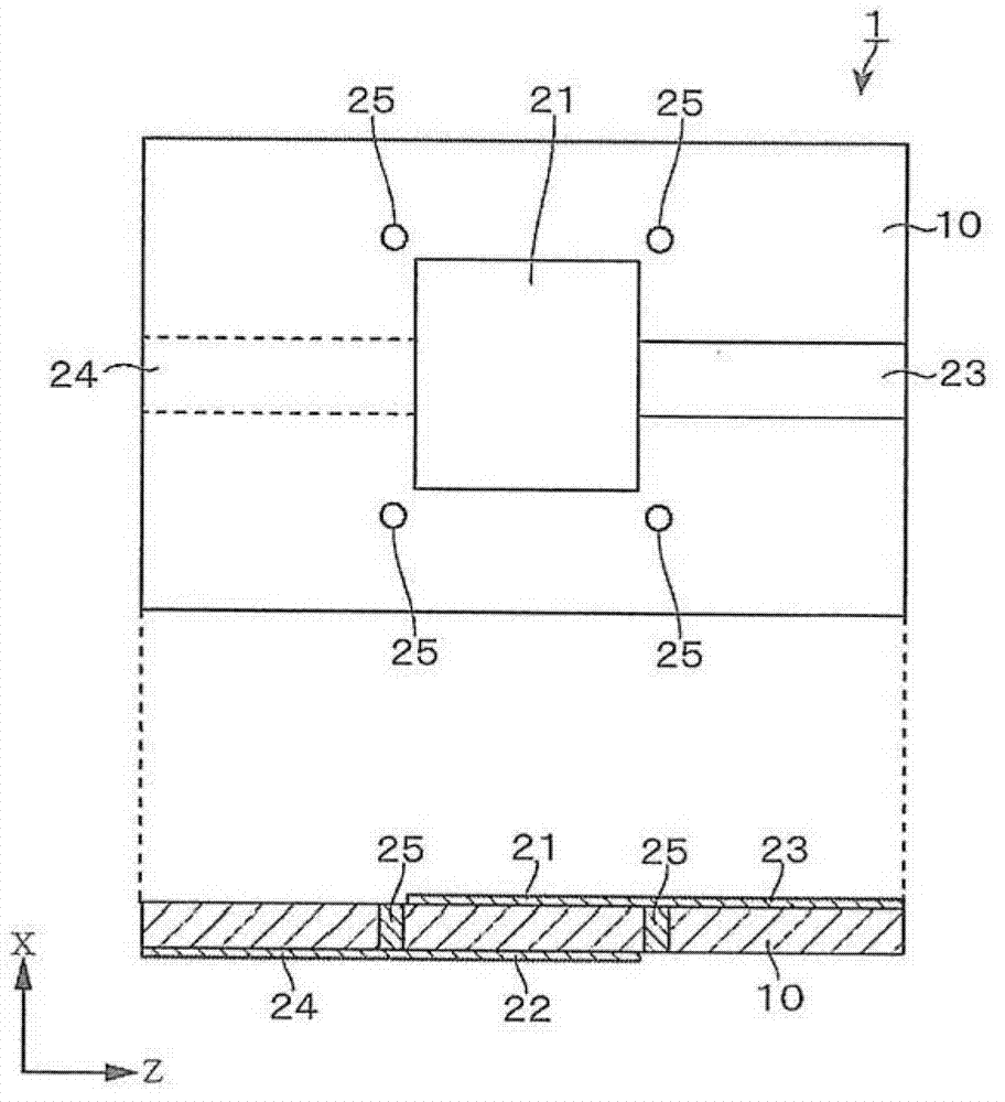
[0089] Hereinafter, an embodiment of a crystal oscillator forming the piezoelectric vibrator of the present invention will be described. Such as figure 1 As shown, this crystal oscillator 1 is configured by providing excitation electrodes 21 and 22 on both surfaces of a piezoelectric crystal plate 10 , respectively. The crystal plate 10 is, for example, an AT-cut crystal plate in the fundamental mode, and is configured to oscillate at 38.4 MHz with thickness-shear vibration as the main vibration. As an example of this embodiment, the planar shape of the crystal plate 10 is, for example, a rectangle such as a rectangle, and its dimensions are set to 1.0 mm in length×0.8 mm in width, and its thickness is set to 43.2 μm.

[0090] In order to excite the crystal plate 10 , excitation electrodes 21 and 22 are formed at the center of both surfaces of the crystal plate 10 so as to face each other. These excitation electrodes 21 and 22 are, for example, square, and one side is approp...

no. 2 approach

[0117] Below, use Figure 5 , another embodiment of the crystal oscillator forming the piezoelectric vibrator of the present invention will be described. If take the Figure 5 The illustrated crystal oscillator 1a is taken as an example to describe the crystal oscillator 1a of this embodiment, and the crystal plate 10 used for the crystal oscillator 1a is, for example, an AT-cut fundamental wave mode crystal plate, and is configured as a main vibration. Thickness shear vibration oscillates at 38.4 MHz. As an example of this embodiment, the planar shape of the crystal plate 10 is, for example, a rectangle such as a rectangle, the dimensions are set to 1.0 mm in length x 1.6 mm in width, and the thickness is set to 43.2 μm.

[0118] In the present embodiment, the axis of a part of the crystal plate 10 in the shape of a belt is reversed to make it twin-crystallized. In this crystal oscillator 1 a , the strip-shaped portion whose axis is inverted is called an axis-inverted port...

Embodiment

[0150] As an example, temperature characteristics of the oscillation frequency were measured for the crystal oscillator of the first embodiment. As a comparative example, for Figure 13 The crystal oscillator of the first embodiment shown in which the secondary vibration suppressing unit 25 is removed, that is, the conventional crystal oscillator was used to measure the temperature characteristics of the oscillation frequency, and this was used as a comparative example.

[0151] The crystal oscillator used for the measurement oscillates in the AT-cut fundamental wave mode, and the oscillation frequency of the main vibration is f 0 = 38.4MHz crystal chip. Regarding the crystal oscillator of the embodiment and the crystal oscillator of the comparative example, in Figure 11 The crystal oscillation circuit shown is used as crystal oscillator 1, the oscillation frequency is measured, and the f 0 The temperature characteristics of the error Δf. Figure 11 Among them, C1~C4 are ...


PUM


Abstract

The present invention provides a piezoelectric resonator that suppresses occurrence of secondary vibration. Crystal oscillators of excitation electrodes are formed respectively on two surfaces of a crystal sheet with thickness-shear vibration as the main vibration. A secondary vibration suppression portion with a crystallographic axis being inverted by heat treatment is disposed at a part where the secondary vibration such as profile-shear vibration, flexure vibration or the like is generated in the crystal sheet. Ideally, a plurality of secondary vibration suppression portions are disposed symmetrically relative to the excitation electrodes. Since the oscillation frequency of the secondary vibration at the part is shifted to a low frequency side, negative effect on the main vibration of the crystal oscillators is suppressed. Therefore, a crystal oscillator having stable frequency characteristics can be obtained.

Description

technical field [0001] The present invention relates to a piezoelectric vibrator that suppresses the occurrence of secondary undulation, an etching amount detection device and an oscillator using the piezoelectric vibrator. Background technique [0002] Piezoelectric vibrators are used in many fields such as electronic equipment, measuring equipment, and communication equipment. However, recently, users have increasingly demanded miniaturization and low price. The fact that oscillators have emerged also makes clear how fierce the competition is. [0003] On the other hand, in piezoelectric vibrators, further improvement in frequency stability is required. In particular, crystal oscillators with AT-cut thickness-shear vibration as the main vibration are widely used because of their good frequency characteristics, but generation of unwanted side vibrations is a problem. As one of the causes of secondary vibration, for example, when thickness shear vibration is the main vibra...

Claims


Application Information

Patent Timeline
Patent Type & Authority Applications(China)
IPC IPC(8): H03H9/19H03H9/02H03H3/04
CPCH03H9/545H03L1/028H03H9/19H03H3/04G01N29/12G01R23/02H03B1/04H03H9/02086
Inventor 小山光明武藤猛石川学佐藤信一
Owner NIHON DEMPA KOGYO CO LTD
Why Eureka
Try Eureka