
Bias control device and method suitable for dual-polarization IQ modulator

A technology of IQ modulator and bias voltage control, applied in the direction of electromagnetic wave transmission system, electrical components, transmission system, etc., can solve the problems of system performance degradation, insignificant change of optical power, no dual polarization modulator, etc.

Active Publication Date: 2014-02-19
WUHAN POST & TELECOMM RES INST CO LTD
View PDF5 Cites 32 Cited by
  • Summary
  • Abstract
  • Description
  • Claims
  • Application Information

AI Technical Summary

Problems solved by technology

However, research on bias voltage control suitable for OFDM (Orthogonal Frequency Division Multiplexing) systems is still relatively small, and there is almost no research on dual polarization modulators.
In theory, the bias voltage can be controlled by detecting the output optical signal power of the OFDM modulated signal, but in practical applications, the optical power near the optimal static operating point does not change significantly, and the impact of device noise is enough to cause the operating point to deviate from the optimum. good points, leading to system performance degradation

Method used


Image

  • Bias control device and method suitable for dual-polarization IQ modulator
  • Bias control device and method suitable for dual-polarization IQ modulator

Examples


Embodiment Construction

[0033] The present invention will be further described in detail below in conjunction with the accompanying drawings and specific embodiments.

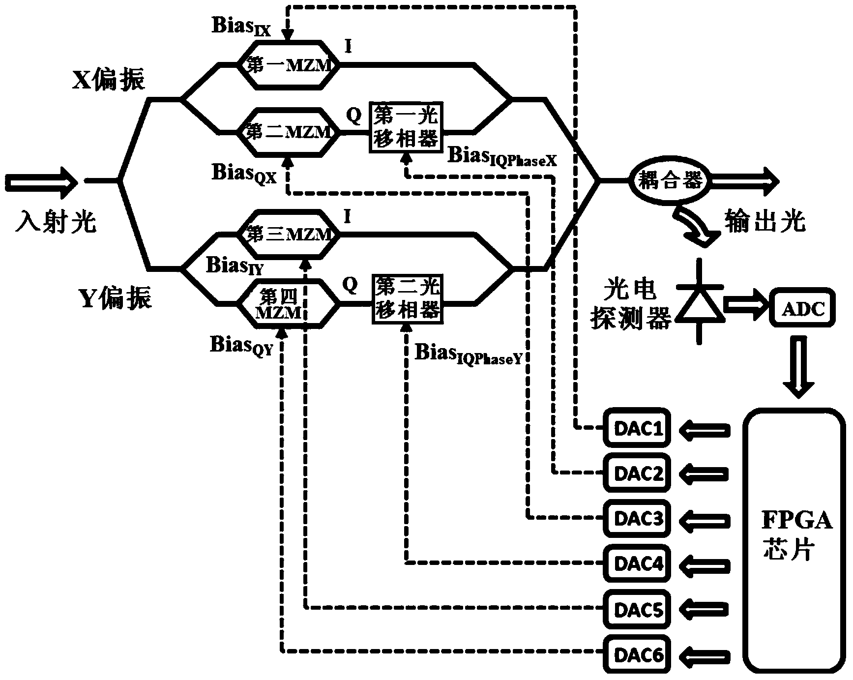
[0034] see figure 1 As shown, the embodiment of the present invention provides a bias voltage control device suitable for a dual-polarization IQ modulator. The dual-polarization IQ modulator includes an X polarization arm, a Y polarization arm, a first MZM, a second MZM, a third MZM, and a second MZM. Four MZMs, the first optical phase shifter and the second optical phase shifter, the X polarization arm and the Y polarization arm both include an I path and a Q path, the I path of the X polarization arm has the first MZM, and the Q path of the X polarization arm has a The second MZM and the first optical phase shifter, the third MZM is arranged on the I road of the Y polarization arm, the fourth MZM and the second optical phase shifter are arranged on the Q road of the Y polarization arm, and the bias control device includes a splittin...


PUM


Abstract

The invention discloses a bias control device and method suitable for a dual-polarization IQ modulator, and relates to the field of optical signal modulation. The bias control device comprises an optical coupler, a photoelectric detector, an ADC and an FPGA chip, wherein the optical coupler, the photoelectric detector, the ADC and the FPGA chip are connected in sequence, and the FPGA chip is respectively connected with a first DAC, a second DAC, a third DAC, a fourth DAC, a fifth DAC and a sixth DAC, and controls the bias of the modulator through the DAC. The method comprises the steps of determining the initial value of an IQ bias voltage by minimizing the output optical power of the modulator, respectively overlapping low-frequency low-amplitude dither signals on the IQ bias voltage, and achieving the accurate control over the IQ bias voltage and a phase difference bias voltage through an iterative algorithm.

Description

technical field [0001] The invention relates to the field of optical signal modulation, in particular to a bias voltage control device and method suitable for a dual-polarization IQ modulator. Background technique [0002] At present, optical communication is developing towards higher speed and higher capacity. In high-speed optical transmitters, the modulation of optical signals usually requires the use of dual MZM (Mach-Zehnder Modulator)-based Polarized IQ (In-phase Quadrature) modulator. However, the optical IQ modulator itself is easily affected by some environmental factors such as temperature, etc., which will cause its static operating point to shift and degrade the system performance. In order to ensure the stability of the signal quality without affecting the system performance, it is necessary to monitor and control the bias voltage of the two polarization arms of the IQ modulator at the same time, so that both polarization arms work at the best static operating ...

Claims


Application Information

Patent Timeline
Patent Type & Authority Applications(China)
IPC IPC(8): H04B10/516H04B10/548
Inventor 张旭王元祥孟令恒杨奇黎偲
Owner WUHAN POST & TELECOMM RES INST CO LTD
Learn More