Air conditioner

An air conditioner and internal air technology, which is applied in air conditioning systems, mechanical equipment, machines/engines, etc., can solve problems such as difficulty in preventing reverse suction, and achieve the effect of preventing the reduction of fan performance and achieving low power and high air volume.

Active Publication Date: 2014-02-19
MITSUBISHI ELECTRIC CORP
View PDF8 Cites 5 Cited by
  • Summary
  • Abstract
  • Description
  • Claims
  • Application Information

AI Technical Summary

Problems solved by technology

Therefore, there is a problem that it is difficult to prevent sucking back that occurs through a gap between a member having a flared outer peripheral surface and the side wall.

Method used


Image

  • Air conditioner
  • Air conditioner
  • Air conditioner

Examples


Embodiment approach 1

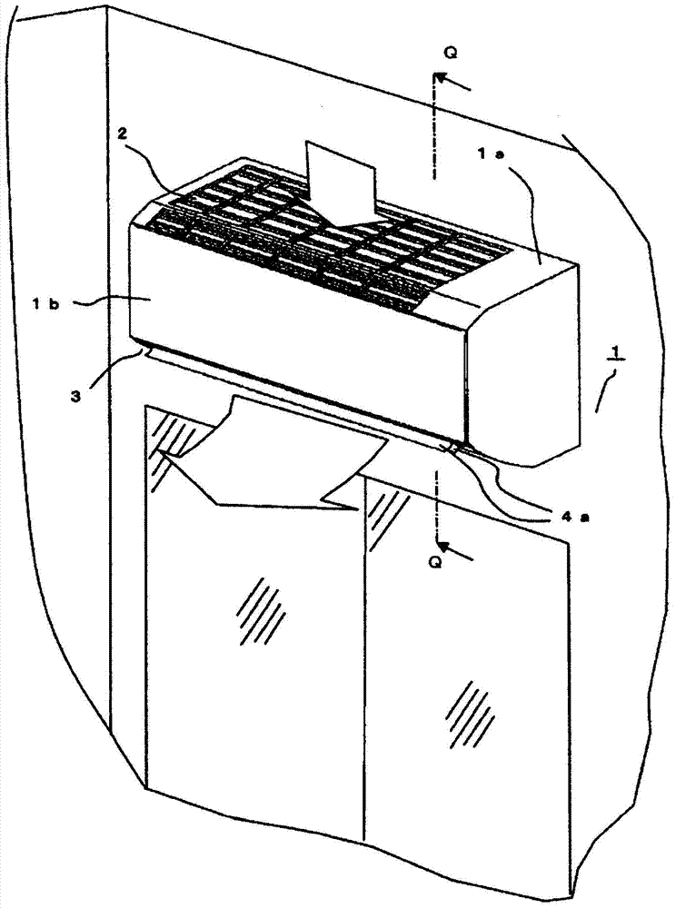
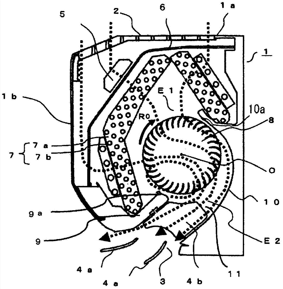
[0049] Hereinafter, Embodiment 1 of the present invention will be described based on the drawings. figure 1 is an external perspective view showing an indoor unit 1 of an air conditioner equipped with a cross-flow fan 8 according to this embodiment, figure 2 yes figure 1 A longitudinal sectional view of the Q-Q line. exist figure 1 , the air flow is indicated by a blank arrow, in figure 2 In , the air flow is indicated by dashed arrows. The air conditioner actually consists of an indoor unit and an outdoor unit to form a refrigeration cycle, but here the structure of the indoor unit is involved, and the structure of the outdoor unit is omitted. Such as figure 1 as well as figure 2 As shown, an indoor unit (hereinafter, referred to as an indoor unit) 1 of an air conditioner has an elongated substantially rectangular parallelepiped shape extending in the left-right direction, and is installed on a wall of a room. On the upper part 1a of the main body of the indoor unit...

Embodiment approach 2

[0081] Figure 17 It is an explanatory diagram showing superimposed wing cross-sections of the air outlet facing wing 13 b and the collision wall facing wing 13 a in the end unit 14 a of the cross-flow fan 8 according to Embodiment 2 of the present invention, and shows a cross section perpendicular to the rotation axis 17 . In the drawings, the same reference numerals as in Embodiment 1 denote the same or corresponding parts. The shape of the indoor unit 1 of the air conditioner near the end unit 14a is the same as that of the first embodiment. Figure 1 to Figure 9 Same shape as shown. Similar to Embodiment 1, in the fan extension portion 8a, the collision wall facing wing 13a facing the collision wall 18 and the blowing outlet facing wing 13b facing the blowing outlet 3 have different wing shapes, especially in this embodiment. In 2, the outlet angle α is configured differently at the blade outer peripheral end portions Ga, Gb.

[0082] Here, the exit angle α will be des...

Embodiment approach 3

[0094] Figure 21 It is Embodiment 3 of the present invention, and is an explanatory diagram showing superimposed wing sections of the air outlet facing wing 13b and the collision wall facing wing 13a in the end unit 14a of the cross-flow fan 8 used in the air conditioner, A section perpendicular to the axis of rotation 17 is shown. In the drawings, the same reference numerals as in Embodiment 1 denote the same or corresponding parts. The shape of the indoor unit 1 near the end unit 14a is the same as that of the first embodiment. Figure 1 to Figure 9 Same shape as shown. Similar to Embodiment 1, the wings of the fan extension 8a facing the collision wall 18, that is, the collision wall facing wing 13a and the blowing outlet facing wing 13b facing the blowing outlet 3 adopt different wing shapes, especially in the Embodiment 3 is characterized in that the warp angle β is configured differently in the blade cross section. In a section perpendicular to the rotation axis 17 ...


PUM


Abstract

There is obtained an air conditioner capable of minimizing backflow of indoor air from indoors to the interior of an air conditioner at the two longitudinal-direction end parts of an air outlet in an indoor unit of the air conditioner, and capable of maintaining the high flow rate of a blower, thereby reducing noise and power consumption. The length of a cross-flow fan (8) in the axial direction of rotation (AX) is greater than the lengthwise-direction length of the air outlet (3), and the cross-flow fan (8) has an extension (8a) that projects from the two ends of the air outlet (3) in the axial direction of rotation (AX). Also provided is a collision wall (18) with which the airstream discharged from the extension (8a) of the cross-flow fan (8) collides, the collision wall being disposed in the air conditioner body. Vanes (13a) on the extension (8a) of the cross-flow fan (8) and vanes (13b) facing the air outlet (3) have different shapes and are configured so that the flow rate of the airstream discharged from the vanes (13a) is less than the flow rate of the airstream discharged from the vanes (13b).

Description

technical field [0001] The present invention relates to an air conditioner, and particularly relates to an indoor unit of a separate air conditioner having an indoor unit and an outdoor unit. Background technique [0002] The indoor unit of the air conditioner is installed indoors where air conditioning is performed (indoors such as houses or companies), and the indoor air sucked in from the suction port exchanges heat with the refrigerant circulating in the refrigeration cycle in the heat exchanger. In the heating operation, the indoor air is heated, and in the cooling operation, the indoor air is cooled, and then the air is blown into the room from the outlet. Therefore, a fan and a heat exchanger are accommodated inside the indoor unit main body. [0003] There are various types of indoor units of air conditioners, but it is known that a cross-flow fan (also called a through-flow fan, a cross-flow fan, or cross flow fan). With respect to the air flow from the suction in...

Claims


Application Information

Patent Timeline
Patent Type & Authority Applications(China)
IPC IPC(8): F24F1/00F04D17/04
CPCF24F13/24F24F1/0025F24F7/007F04D29/522F04D17/04F24F1/0011F04D29/4226
Inventor 田所敬英池田尚史滨田慎悟代田光宏
Owner MITSUBISHI ELECTRIC CORP
Why Eureka
Try Eureka