Bearing lubricating system of coal mill

A bearing lubrication and lubrication system technology, applied in the direction of engine lubrication, lubricating parts, mechanical equipment, etc., can solve the problems of long running time of oil pumps, equipment affecting the environment, affecting safety production, etc., to save maintenance funds and operating costs, Good filtering effect, ensure healthy effect

Inactive Publication Date: 2014-02-26
CHINA COAL ENERGY HEILONGJIANG COAL CHEM
View PDF9 Cites 4 Cited by
  • Summary
  • Abstract
  • Description
  • Claims
  • Application Information

AI Technical Summary

Problems solved by technology

[0003] The present invention aims to solve the problem that the coal mill bearing lubrication system in the prior art works due to the long running time of the oil pump, which leads to large mechanical wear, and the frequent adjustment of the oil volume, often resulting in excessive oil, low oil, or oil cut-off, resulting in burning and damage to the bearing. The phenomenon of equipment affecting the environment and affecting production safety, due to the large noise and dusty environment on the site, has brought physical and mental damage to the staff who have been working on the site, and the problem of low work efficiency, and then provides a coal mill bearing lubrication system

Method used


Image

  • Bearing lubricating system of coal mill

Examples


specific Embodiment approach 1

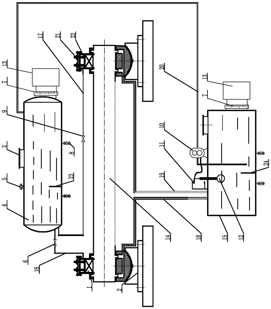
[0007] Specific implementation mode one: combine figure 1 Describe this embodiment, a coal mill bearing lubrication system described in this embodiment, the lubrication system includes a sponge body 1, a high oil tank 4, an oil pump 10, a limit contactor 11, a float 12, a shaft 14, and a low oil tank 15. The first oil inlet pipe 16, the second oil inlet pipe 17, the first oil outlet pipe 18, the second oil outlet pipe 19, the oil return pipe 20, the screw adjustment rod 21, the pressure plate 22, two bearing seats with bearings 2, two The liquid level gauge 7 and two liquid level control boxes 13, the top of the high oil tank 4 and the top of the low oil tank 15 are all processed with manholes 3, and the top of the bearing block 2 with bearings is provided with an oil storage tank, each oil storage tank There is a sponge body 1 inside, the screw adjustment rod 21 is fixed on the upper end surface of the pressure plate 22, the pressure plate 22 is set in the oil storage tank, a...

specific Embodiment approach 2

[0008] Specific implementation mode two: combination figure 1 Describe this embodiment, the coal mill bearing lubrication system described in this embodiment, the high oil tank 4 includes a first oil tank partition 23, the low oil tank 15 includes a second oil tank partition 24, the first oil tank partition 23 is vertical It is vertically arranged on the inner wall of the bottom of the high fuel tank 4, and the second fuel tank partition 24 is vertically arranged on the inner wall of the bottom of the low fuel tank 15. Others are the same as in the first embodiment.

specific Embodiment approach 3

[0009] Specific implementation mode three: combination figure 1 Describe this embodiment, a coal mill bearing lubrication system described in this embodiment, the lubrication system also includes four blowdown valves 8, two blowdown valves 8 are installed at the bottom of the high oil tank 4 and the low oil tank 15, other It is the same as the first embodiment.


PUM


Abstract

The invention relates to a bearing lubricating system of a coal mill. The bearing lubricating system aims to solve the problems that in the prior art, when a bearing lubricating system of a coal mill works, the running time of an oil pump is too long, machine abrasion is serious, the oil quantity is frequently adjusted, much oil or less oil or oil breaking occurs, the phenomena of burning a bearing, damaging equipment and influencing environment and safety production occur, due to the fact that field noise is high, much dust exists and the environment is poor, the mind and body of work staff on the work field all the time are hurt, and work efficiency is low. The lubricating system comprises a sponge body, a high-position oil tank, an oil pump, a limit contact device, a floater, a shaft, a low-position oil tank, a first oil inlet pipe, a second oil inlet pipe, a first oil outlet pipe, a second oil outlet pipe, an oil return pipe, a spiral adjusting rod, a press plate, two bearing seats with bearings, two liquid level meters and two liquid level control boxes. The bearing lubricating system is used for bearing lubricating systems of coal mills.

Description

technical field [0001] The invention relates to a coal mill bearing lubricating system. Background technique [0002] The existing coal mill bearing lubrication system is mechanical lubrication. The operation is to start the gear oil pump first, and then adjust the oil supply and cooling water of the front bearing of the coal mill, the oil supply and cooling water of the rear bearing, and the oil supply of the gear reducer. and cooling water, start the coal mill after all adjustments are completed. For mechanical lubrication, the amount of oil is not only difficult to adjust, the adjustment is uneven, and the amount of oil often changes. Such frequent adjustment operations make it impossible for the on-duty personnel to leave the milling site. The site is noisy and dusty and the environment is poor, which seriously affects the physical and mental health of employees. Increased the labor intensity of the staff on duty. Bearings are one of the vulnerable parts, and mechanica...

Claims


Application Information

Patent Timeline
Patent Type & Authority Applications(China)
IPC IPC(8): F16N7/40F16N31/00
Inventor 王跃伦初海滨王伟东刘跃张学权王洪升
Owner CHINA COAL ENERGY HEILONGJIANG COAL CHEM
Why Eureka
Try Eureka