A small stretching and bending device

A tensile-bending and bending technology, which is applied in the field of micro-nano tensile-bending single and composite mechanical properties testing devices, can solve problems such as restricting the rapid development of micro-nano tensile-bending mechanical testing technology, and achieve compact and delicate structure. , the effect of large bending loading force

Inactive Publication Date: 2015-11-04
CHANGCHUN UNIV OF TECH
View PDF6 Cites 0 Cited by
  • Summary
  • Abstract
  • Description
  • Claims
  • Application Information

AI Technical Summary

Problems solved by technology

At present, micro-nano bending mechanical tests are mainly carried out in transmission electron microscope (TEM) and scanning electron microscope (SEM), both of which have very limited working chambers, and it is necessary to ensure the electromagnetic compatibility and Vacuum compatibility, it is these reasons that limit the rapid development of micro-nano tensile bending mechanics testing technology
Overall, it is still a challenging task to study a micro-nano tensile-bending composite mechanical testing device with high precision, large testing range, and low cost, and it is also an urgent task.

Method used


Image

  • A small stretching and bending device
  • A small stretching and bending device
  • A small stretching and bending device

Examples


Embodiment Construction

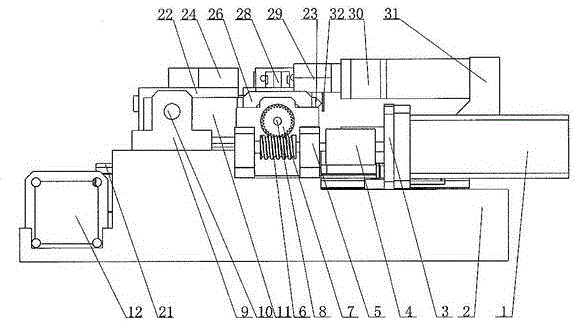
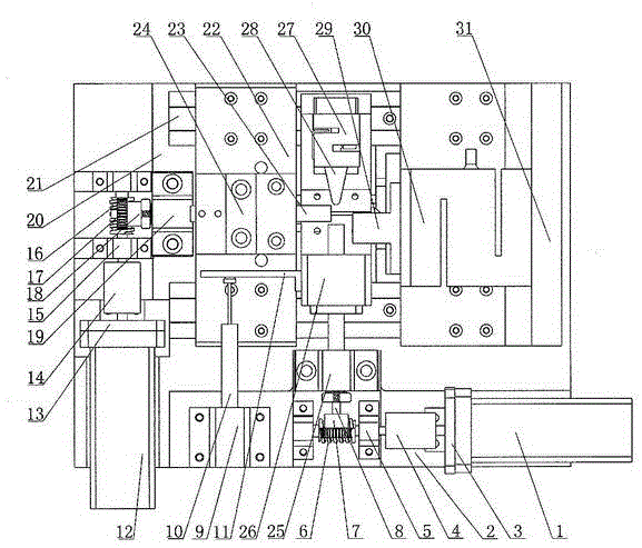
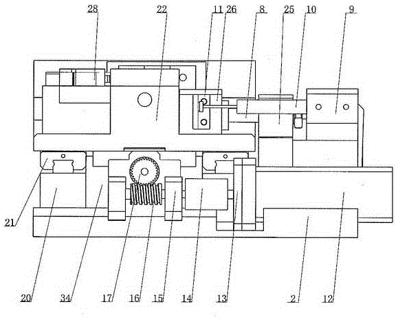
[0018] See figure 1 , figure 2 , image 3 with Figure 4 As shown, the present invention is composed of a bending loading mechanism, a specimen clamping mechanism, a tensile loading mechanism, and a bending displacement measuring device. The bending loading mechanism is composed of a first motor 1, a first motor flange 3, and a first motor flange 3. The coupling 4, the first worm 6, the first worm gear 7, the one-way screw nut pair 8, the first screw support base 25, the fourth support 26, the first tension and pressure sensor 27, and the bending head 28, The drive first motor 1 is fixedly installed on the base 2 through the first motor flange 3, the motor output shaft and the first worm 6 are connected through the first coupling 4, and the first worm 6 and the first worm gear 7 form a one-stage reduction And reversing, the first worm gear 7 is installed on the one-way screw nut pair 8, and then installed on the base 2 through the first screw support seat 25, the one-way screw...


PUM


Abstract

The invention discloses a small stretch bending device, which is composed of a bending loading mechanism, a test piece clamping mechanism, a stretch loading mechanism and a bending displacement measuring apparatus. The stretch loading mechanism drives first stage worm and gear through a motor, then a bidirectional lead screw-nut pair converts curve motion into linear motion, a tensile force is loaded to two ends of a test piece clamp, and then the tensile force is loaded to the test piece. One end of the clamp is equipped with a tension-compression sensor for detecting the tensile force borne by the test piece. The stretch displacement can be monitored at any time through a contact type displacement sensor installed below the clamp. The bending loading mechanism drives a worm and gear through a motor, and then a unidirectional lead screw-nut pair converts curve motion into linear motion so as to drive a base mounted on the lead screw and a bending pressure head to realize reciprocating motion. The bending displacement can be detected by the contact type displacement sensor installed on the base. The bending pressure head is also equipped with a miniature tension-compression sensor for detecting the stress of the pressure head during bending.

Description

Technical field [0001] The invention relates to a device with a small volume and an exquisite structure that can be used for testing single and composite mechanical properties of materials in micro-nano stretching and bending. Through the invention, the test piece can be subjected to in-situ tensile and bending tests under the observation of various imaging instruments, and the in-situ observation of the microscopic deformation and damage process of the material can be carried out. This device will have good application prospects in the fields of materials science, super processing, solid mechanics and so on. Background technique [0002] In-situ micro-nano mechanics testing technology is a cutting-edge technology developed in recent years and has attracted great attention from governments and research institutions in various countries. The micro-nano tensile and bending mechanics testing technology has many advantages that it can perform in-situ tensile, bending and composite t...

Claims


Application Information

Patent Timeline
Patent Type & Authority Patents(China)
IPC IPC(8): G01N3/16G01N3/20G01N3/06
Inventor 崔利娜江虹韩顺杰陈月岩矫德强黄艳秋袁守彬王一冰王文武
Owner CHANGCHUN UNIV OF TECH
Why Eureka
Try Eureka