Device and method for measuring bus voltage phase of capacitor voltage transformer

A voltage transformer, bus voltage technology, applied in the direction of measuring device, phase angle between voltage and current, measuring electrical variables, etc., can solve the problems of complicated wiring, occupying CVT output capacity, poor real-time performance, etc., and achieve safe and reliable work , broad application prospects, simple wiring effect

Active Publication Date: 2014-02-26
STATE GRID CORP OF CHINA +3
View PDF11 Cites 18 Cited by
  • Summary
  • Abstract
  • Description
  • Claims
  • Application Information

AI Technical Summary

Problems solved by technology

In the prior art, the reference phase of the on-line monitoring system for capacitive equipment and metal oxide arresters is the output voltage of the CVT secondary side. Since the method of directly collecting the voltage of the CVT secondary side is adopted, this requires the CVT secondary side output voltage. The secondary side voltage output terminal is connected to a voltage coupling device, and its disadvantages are: the connected voltage coupling device will occupy a certain amount of CVT output capacity, and the connected equipment will increase the risk of short circuit on the secondary side of the CVT, and the error characteristics of the CVT are not as good as the electromagnetic type The voltage transformer is stable, and the system frequency, CVT secondary load size and power factor changes will introduce additional errors
Although the accuracy of CVT can reach 0.2, these additional errors will still have a great impact on the insulation on-line monitoring
An improved method was proposed in "Error Correction of Capacitive Voltage Transformer in Insulation On-line Monitoring" published by Sun Jiantao et al. In this method, a current transformer is connected in series in each circuit of the CVT secondary side, which makes this method in The wiring is complicated during the implementation process, the fitting function method used in this paper has a large amount of calculation, poor real-time performance, and the calculation accuracy is related to the number of iterations
In addition, this reference phase measurement method still requires a voltage coupling device to be connected to the secondary side of the CVT, which does not eliminate potential risks in the operation of the CVT

Method used


Image

  • Device and method for measuring bus voltage phase of capacitor voltage transformer
  • Device and method for measuring bus voltage phase of capacitor voltage transformer
  • Device and method for measuring bus voltage phase of capacitor voltage transformer

Examples


Embodiment Construction

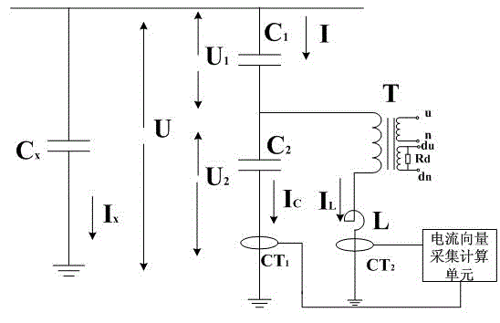
[0024] The busbar voltage phase measuring device of the capacitive voltage transformer of the present invention, such as figure 1 shown, including:

[0025] The first current transformer CT1, the first current transformer CT1 is connected to the ground terminal of the medium voltage capacitor C2 of the capacitive voltage transformer, and is used to collect the ground current of the medium voltage capacitor C2;

[0026] The second current transformer CT2, the second current transformer CT2 is connected to the ground terminal of the intermediate transformer T1 of the capacitive voltage transformer, and is used to collect the ground current of the intermediate transformer T1;

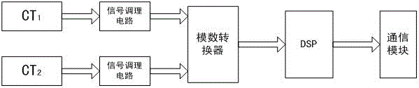
[0027] A current vector acquisition calculation unit, the current vector acquisition calculation unit is connected to the output terminals of the first current transformer and the second current transformer, so as to process the collected current signal and convert it into a digital signal, and then pass ...


PUM


Abstract

The invention relates to a device and method for measuring a bus voltage phase of a capacitor voltage transformer. The device comprises a first current transformer, a second current transformer and a current vector collection and computation unit. The method comprises the following steps: connecting the first current transformer and the second current transformer into a ground terminal of a middle voltage capacitor and a ground terminal of a middle transformer of the capacitor voltage transformer respectively, respectively feeding coupled current signals into the current vector collection and computation unit by the first current transformer and the second current transformer, conducting processing such as amplification and filtering on collected current signals, converting the current signals into digital signals, and computing the numerical value to obtain the instantaneous phase of the bus voltage of the capacitor voltage transformer. The device and method are accurate in measuring, good in real-time performance, simple in wiring, small in influence on the capacitor voltage transformer, safe and reliable.

Description

technical field [0001] The invention relates to the technical field of on-line monitoring of power system substation equipment, in particular to a bus voltage phase measurement device and method of a capacitive voltage transformer. Background technique [0002] In the existing open-type substations with a voltage level of 220kV and above, most of the voltage transformers are capacitive voltage transformers (CVT). In the prior art, the reference phase of the on-line monitoring system for capacitive equipment and metal oxide arresters is the output voltage of the CVT secondary side. Since the method of directly collecting the voltage of the CVT secondary side is adopted, this requires the CVT secondary side output voltage. The secondary side voltage output terminal is connected to a voltage coupling device, and its disadvantages are: the connected voltage coupling device will occupy a certain amount of CVT output capacity, and the connected equipment will increase the risk of ...

Claims


Application Information

Patent Timeline
Patent Type & Authority Applications(China)
IPC IPC(8): G01R25/00
Inventor 廉彦超陈彬陈敏维范元亮吴勇昊
Owner STATE GRID CORP OF CHINA
Why Eureka
Try Eureka