Laser light power self-adaptation control method based on MCU

An adaptive control and laser technology, applied in the field of lasers, can solve the problems of unusable optical transmission modules, low availability of optical transmission modules, changes in laser luminous power, etc. The effect of labor costs

Active Publication Date: 2014-02-26
WUHAN HONGXIN TELECOMM TECH CO LTD
View PDF5 Cites 12 Cited by
  • Summary
  • Abstract
  • Description
  • Claims
  • Application Information

AI Technical Summary

Problems solved by technology

[0002] The control of the optical power of the laser in the existing optical transmission module is mainly to control the luminous power of the laser at a fixed power value through the hardware circuit, but as the ambient temperature of the optical transmission module changes, the luminous power of the laser will change. It has...

Method used


Image

  • Laser light power self-adaptation control method based on MCU
  • Laser light power self-adaptation control method based on MCU
  • Laser light power self-adaptation control method based on MCU

Examples


Embodiment Construction

[0038] In order to make the purpose, technical solutions and advantages of the present invention more clear, the present invention will be further described in detail with reference to the accompanying drawings and embodiments below:

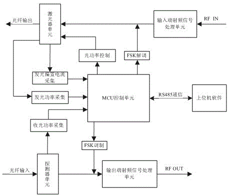
[0039] The Chinese name of MCU (Micro Control Unit) is a micro control unit, such as figure 1 The system used for MCU laser control in the prior art shown includes an MCU control unit, a laser unit, a detector unit, a radio frequency signal processing unit at an input end, and a radio frequency signal processing unit at an output end. The output of the laser unit is output through the optical fiber, the input of the detector unit is input through the optical fiber, the input RF signal of the RF signal processing unit at the input end is marked as RF IN, and the output RF signal of the RF signal processing unit at the output end is marked as RF OUT.

[0040] The system generally sets the RF input port, and the RF signal RF IN is input from the RF...


PUM


Abstract

The invention discloses a laser light power self-adaptation control method based on an MCU. An MCU control unit is communicated with an upper computer. The upper computer is used for setting the self-adaptation control modes as laser bias current regulation or laser light power regulation. When laser light power regulation is adopted, self-adaptation control is carried out by the MCU control unit according to the target luminous power value set by the upper computer and the actual luminous power value for laser sampling. When laser bias current regulation is adopted, self-adaptation control is carried out by the MCU control unit according to the target bias current value set by the upper computer and the actual bias current value for laser sampling. By means of the laser light power self-adaptation control method, the luminous power and the bias current of a laser can be kept constant, hardware regulation is not needed, the constant value of the light power of the laser can be changed through the upper computer, the same light transmission module can be used in other complete machines with different demands, and the utilization rate of the laser is greatly improved.

Description

technical field [0001] The invention relates to the field of lasers, in particular to an MCU-based adaptive control method for laser optical power. Background technique [0002] The control of the optical power of the laser in the existing optical transmission module is mainly to control the luminous power of the laser at a fixed power value through the hardware circuit, but as the ambient temperature of the optical transmission module changes, the luminous power of the laser will change. It has an impact on the index parameters of the optical transmission module and the whole machine. At the same time, the luminous power value of the optical transmission module is fixed, so that the optical transmission module cannot be used in other complete machines, and the availability of the optical transmission module is extremely low. Contents of the invention [0003] In view of this, the object of the present invention is to overcome the above-mentioned technical shortcomings, an...

Claims


Application Information

Patent Timeline
IPC IPC(8): H01S3/10G05D25/02
Inventor 赵舟伟
Owner WUHAN HONGXIN TELECOMM TECH CO LTD
Why Eureka
Try Eureka