Energy converting device for energy systems, and method for operating such device

An energy conversion device and energy equipment technology, applied in energy storage, mechanical equipment, wind turbines that store gravitational potential energy, etc., can solve problems such as reducing the energy output of electrical appliances, and achieve the effect of improving energy efficiency

Inactive Publication Date: 2014-02-26
HYDAC SYST
View PDF11 Cites 4 Cited by
  • Summary
  • Abstract
  • Description
  • Claims
  • Application Information

AI Technical Summary

Problems solved by technology

However, due to multiple energy conversion steps or other measures proposed in the prior art to overcome the "dead point characteristics" of the system, energy losses still occur durin

Method used


Image

  • Energy converting device for energy systems, and method for operating such device
  • Energy converting device for energy systems, and method for operating such device
  • Energy converting device for energy systems, and method for operating such device

Examples


Embodiment Construction

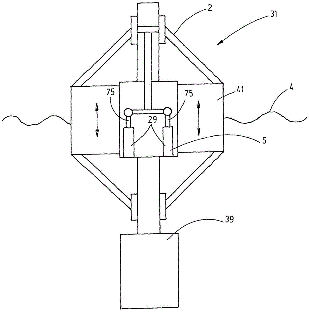
[0029] exist figure 1 The basic structure of the wave device 31 as an energy feed device is shown in a highly simplified schematic functional diagram. The wave device 31 is designed in the form of a buoy and has a first float body as a pile float 39 and a second float body as an annular float 41 radially surrounding the pile float. The pile float 39 has a greater mass than the annular float 41 and in this respect forms a two-mass wave energy device such as that shown in DE 60 115 509 T2 described above. The pile float 39 therefore has a lower natural frequency than the ring float 41 . The annular float 41 is axially movable relative to the pile float 39 . Therefore, the annular buoy 41 is always moved axially relative to the pile buoy 39 by the waves 4 surrounding the wave device 31 and passing by the wave device 31 (at figure 1 Indicated by means of two double-headed arrows), the relative axial movement increases here as the amplitude of the wave motion increases, which le...


PUM


Abstract

The invention relates to an energy converting device for energy systems (2) for converting mechanical energy into hydraulic energy and then into electric energy, said device using a control fluid (3) as the energy transporting medium. The control fluid is subjected to a variably changing pressure by at least one first converting device (5) that converts the mechanical energy into hydraulic energy. The energy converting device comprises at least one second subsequent converting device (7) that converts the hydraulic energy into electric energy. The invention is characterized in that the second converting device (7) is divided into a first control circuit (9) and a second control circuit (11), the two of which can be supplied with the control fluid (3) of variable pressure at the circuit input side (13) by the first converting device (7) and the two of which have predominantly different pressure levels.

Description

technical field [0001] The work devoted to this invention was funded under funding agreement No. 239376 in the process of the European Union's Seventh Framework Program (RP7 / 2007-2013). [0002] The invention relates to an energy conversion device for an energy plant for converting mechanical energy into hydraulic energy and further into electrical energy, said energy conversion device using a control fluid as energy transmission medium which converts mechanical energy from at least one A first conversion unit which converts hydraulic energy into hydraulic energy obtains a variably variable pressure, and the energy conversion device has at least one downstream second conversion unit which converts hydraulic energy into electrical energy. Furthermore, the invention relates to a method for operating the device. Background technique [0003] The exploitable environmental energy also includes wave energy, whose energy potential can cover at least about 15% of the global electri...

Claims


Application Information

Patent Timeline
IPC IPC(8): F03B13/00F03D9/00F03D9/02
CPCY02E60/15F03D9/028Y02E10/38Y02E10/72F03B13/00F03D9/001F05B2260/406F03D9/17F03D9/28Y02E10/30Y02E60/16Y02E70/30F03B13/14
Inventor K·施莱默N·伯默尔F·福克斯舒默
Owner HYDAC SYST
Why Eureka
Try Eureka