Welding gun clamping structure

A clamping structure and welding torch technology, applied in welding equipment, auxiliary welding equipment, welding/cutting auxiliary equipment, etc., can solve the problems of high cylinder pressure requirements, lack of tracking effect, influence of welding torch moving speed, etc., to achieve improved Welding or cutting quality, effect of constant distance

Inactive Publication Date: 2014-03-05
苏州盟通利环境科技有限公司
View PDF8 Cites 7 Cited by
  • Summary
  • Abstract
  • Description
  • Claims
  • Application Information

AI Technical Summary

Problems solved by technology

However, this structure requires high pressure on the cylinder. If the pressure is small, the tracking effect will not be achieved, and if the pressure is high, it will affect the moving speed of the welding torch.

Method used


Image

  • Welding gun clamping structure

Examples


Embodiment Construction

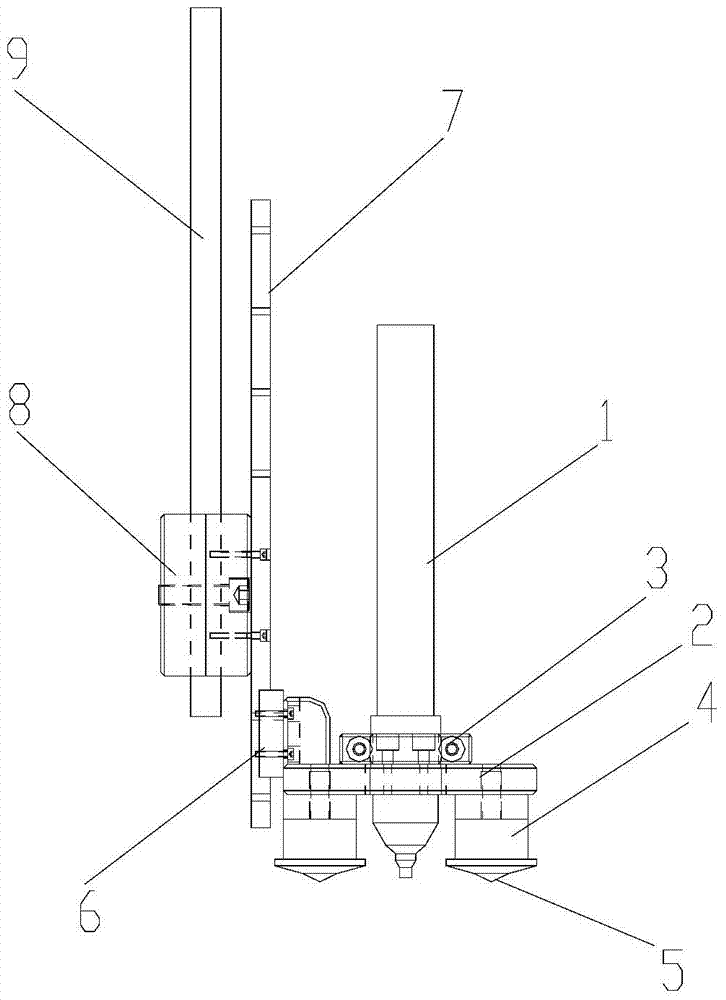
[0012] The implementation of the present invention will be illustrated by specific specific examples below, and those skilled in the art can easily understand other advantages and effects of the present invention from the contents disclosed in this specification.

[0013] see figure 1 . It should be noted that the structures, proportions, sizes, etc. shown in the drawings attached to this specification are only used to match the content disclosed in the specification, for those who are familiar with this technology to understand and read, and are not used to limit the implementation of the present invention. Limiting conditions, so there is no technical substantive meaning, any modification of structure, change of proportional relationship or adjustment of size, without affecting the effect and purpose of the present invention, should still fall within the scope of the present invention. The disclosed technical content must be within the scope covered. At the same time, term...


PUM


Abstract

The invention provides a welding gun clamping structure. A welding gun is fixed to a positioning plate, at least two supporting parts are arranged on the lower surface of the positioning plate, the supporting parts are distributed around the welding gun, the length by which every supporting part extends out of the lower surface of the positioning plate is larger than that by which the welding gun extends out of the lower surface of the positioning plate, the positioning plate is connected with a guide post in a sliding mode, and the guide post is fixedly connected with a machine tool arm. When the welding gun of the clamping structure is adopted for work, the supporting parts are supported on a workpiece to be welded, when a machine tool drives the positioning plate to move on the workpiece to be welded, the supporting parts will move up and down according to the surface shape of the workpiece to be welded, so that it is ensured that the distance between the welding gun and the workpiece to be welded is constant, the welding gun works normally, no influence on the moving speed of the welding gun can be caused, and welding and cutting quality of the welding gun can be effectively improved. The clamping mechanism is easy to machine, low in production cost, easy to achieve and capable of achieving large-scale batch production.

Description

technical field [0001] The invention relates to a clamp structure, in particular to a clamp structure for clamping a welding torch. Background technique [0002] When welding or cutting a workpiece with a welding torch, it is necessary to keep a certain distance between the welding torch and the workpiece so that the welding torch can start the arc. The distance between them remains constant at all times, which will affect the normal operation of the welding torch. For this reason, a tracking mechanism is usually arranged on the welding torch, and the distance between the welding torch and the workpiece can be kept constant by the tracking mechanism. Existing tracking mechanism mainly has two ways of spring compression tracking head and laser probe. Both of the above two methods have certain disadvantages. The tracking force of the spring pressing the tracking head will be affected by the degree of relaxation of the spring itself, which may affect the moving speed of the we...

Claims


Application Information

Patent Timeline
IPC IPC(8): B23K37/02
CPCB23K37/02
Inventor 许正荣麻超朱正萍徐斌
Owner 苏州盟通利环境科技有限公司
Why Eureka
Try Eureka