Automatic locking device of printing plate

An automatic locking and printing plate technology, applied in the general parts of printing machinery, printing, printing machines, etc., can solve the problem of easily scratching the surface of the printing plate cylinder, the long time spent changing the printing plate, and the influence of the degree of fit of the printing plate, etc. problems, to ensure integrity, save printing costs, and secure and reliable results

Active Publication Date: 2014-03-05
GOSS GRAPHIC PRINTING SYST CHINA
View PDF7 Cites 2 Cited by
  • Summary
  • Abstract
  • Description
  • Claims
  • Application Information

AI Technical Summary

Problems solved by technology

However, during the use of the printing press, the centrifugal force generated by the high-speed operation of the printing plate cylinder will cause a gap between the printing plate and the surface of the printing plate cylinder, which will affect the fit of the printing plate
When disassembling the printing plate, it is necessary to manually use a suction cup to pull the plate tip

Method used


Image

  • Automatic locking device of printing plate
  • Automatic locking device of printing plate
  • Automatic locking device of printing plate

Examples


Example Embodiment

[0020] In order to better understand the technical solutions of the present invention, specific embodiments are used in the following to describe in detail with reference to the accompanying drawings.

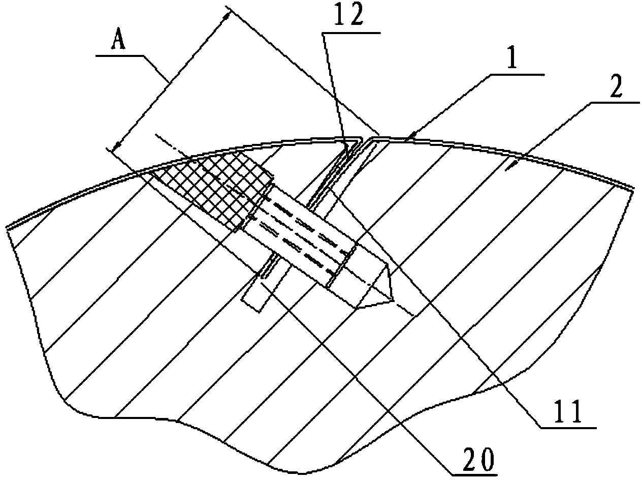
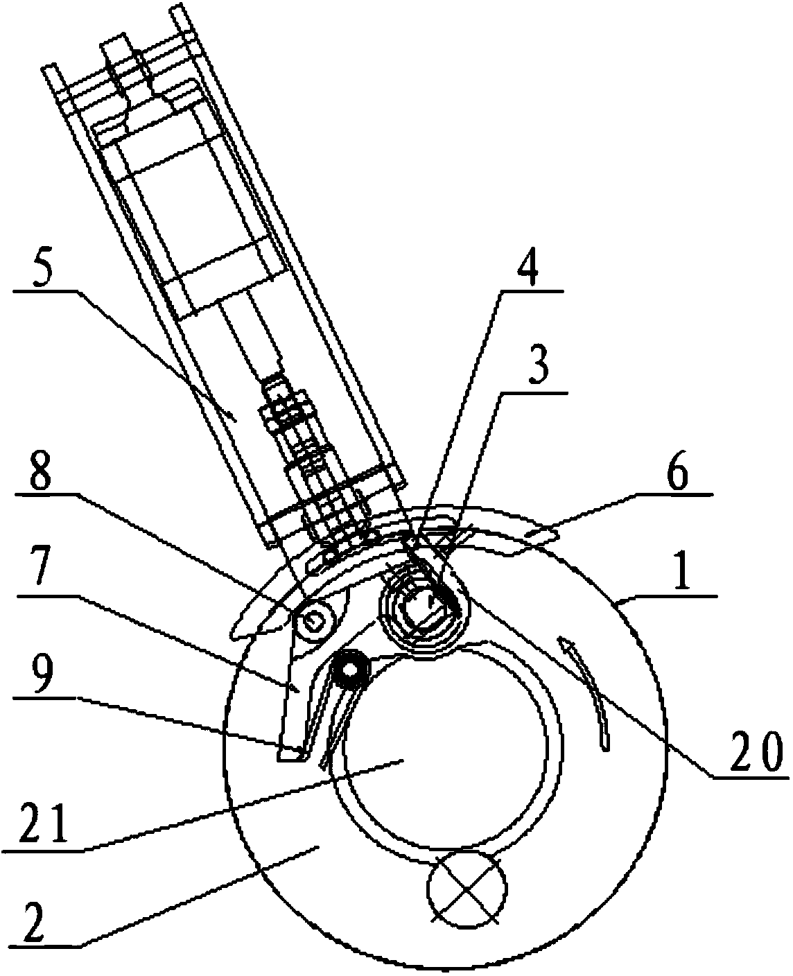
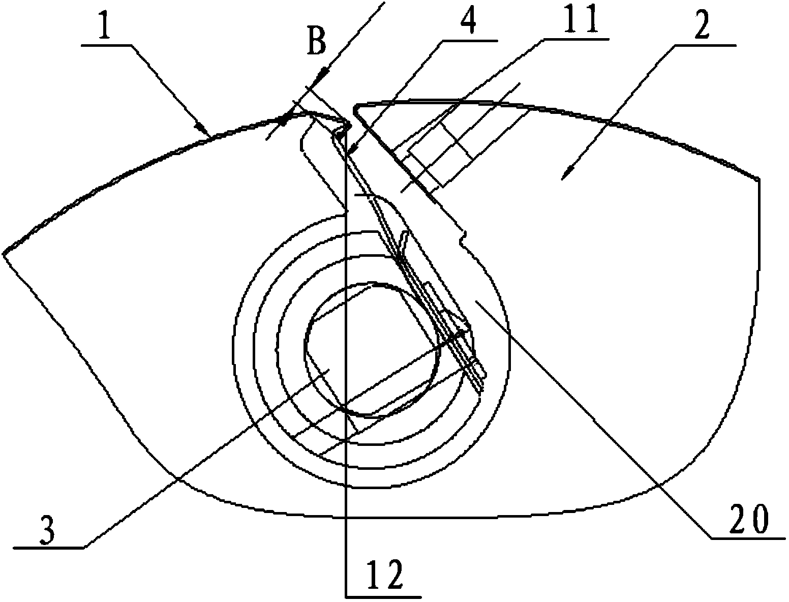
[0021] See Figure 2 to Figure 4 , The automatic locking device of the printing plate of the present invention includes a printing plate cylinder 2 on which a printing plate 1 is installed and a plate groove 20 is axially provided on the surface, and also includes a reel 3, a spring sheet 4, a cylinder 5, a cam 6, Link arm 7, bearing 8 and torsion spring 9, of which,

[0022] The two ends of the printing plate 1 are provided with a plate opening fold 11 and a plate fold 12 corresponding to each other, and the length of the plate fold 1 is B=1.8~2mm;

[0023] The bottom of the plate groove 20 of the plate cylinder 2 is a circular groove, and the upper part is a straight groove, so that the cross section of the plate groove is basically b-shaped, and the mouth of the groove wall on the...


PUM

PropertyMeasurementUnit
Lengthaaaaaaaaaa

Abstract

The invention discloses an automatic locking device of a printing plate. The automatic locking device of the printing plate comprises the installation printing plate, a printing plate roller provided with a plate groove formed in the surface of the printing plate roller in the axial direction, a rolling shaft, a leaf spring, an air cylinder, a cam, a connecting arm, a bearing and a torsion spring. The cross section of the plate groove is basically of a b shape; the rolling shaft is arranged on the lower portion of the plate groove; the leaf spring is inserted into the upper portion of the plate groove, the lower portion of the plate groove is fixedly connected with the rolling shaft, and the upper end of the plate groove is provided with a hooked edge; the air cylinder is installed on the inner side face of a transmission side wall board; the cam is installed on the end of a piston rod of the air cylinder; the head of the connecting arm is fixedly connected to the rolling shaft and a concave arc face is arranged in the middle of the upper surface of the connecting arm; the bearing is arranged on the concave arc face of the connecting arm and continuously pressed by the cam; a body of the torsion spring is arranged on the lower portion of the connecting arm and two torsion arms are located on the tail portion of the lower surface of the connecting arm and the outer surface of the rolling shaft of the printing plate roller correspondingly. The plate end bending edge of the printing plate is connected with the hooked edge of the leaf spring in a hung mode. According to the automatic locking device of the printing plate, the accuracy of printing plate installation is improved and the printing plate is convenient to install and detach.

Description

Technical field [0001] The invention relates to an automatic locking device for printing plates. Background technique [0002] The existing printing plate locking device such as figure 1 As shown, the printing plate 1 is manually installed. When installing, first insert the fold 11 of the printing plate 1 into the plate slot 20 of the printing plate cylinder 2. After the printing plate cylinder 2 rotates one circle, the printing plate is manually installed. The edge fold 12 of the plate tip of 1 is slapped into the plate groove 20. Finally, a rag must be used to wipe the plate groove back and forth twice to ensure that the edge of the plate tip completely enters the plate groove 20 of the plate cylinder 2, and the plate edge fold 11 and The plate tip folds 12 contact each other by restoring elastic force to generate friction, which ensures that the plate tip folds 12 will not pop out of the plate groove 20 of the printing plate cylinder 2. However, during the use of the printing...

Claims


Application Information

Patent Timeline
IPC IPC(8): B41F27/00
Inventor 刘怡丰梁晓峰万云飞何颖琪沈憶雯
Owner GOSS GRAPHIC PRINTING SYST CHINA
Why Eureka
Try Eureka