Caching feeding bin

A feeding bin and cache technology, applied in the field of material storage, can solve the problems of unresolvable materials, large frictional resistance, and increased equipment cost, so as to improve volumetric efficiency, prevent the reduction of feeding function, and eliminate the dead zone of material discharge.

Active Publication Date: 2014-03-05
光大清洁技术股份有限公司
View PDF6 Cites 5 Cited by
  • Summary
  • Abstract
  • Description
  • Claims
  • Application Information

AI Technical Summary

Problems solved by technology

In order to solve this problem, it is necessary to install a discharge carriage at the bottom of the warehouse. Through the reciprocating motion of the carriage, the materials far away from the discharge port are pushed to the discharge port. However, due to the direct friction between the carriage and the bottom of the warehouse, the carriage Affected by the pressure of the material on it and its own weight, the frictional resistance is relatively large, and the larger the storage bin, the greater the frictional resistance. Therefore, for a larger storage bin, a higher-strength carriage and drive are often required. power, which increases the cost of the equipment, and its service life and reliability are also greatly affected, and the excessive power also causes a huge waste of power
On the other hand, the unloading carriage only solves the unloading problem, and cannot solve the requirement that the material be discharged at a relatively constant speed

Method used


Image

  • Caching feeding bin
  • Caching feeding bin
  • Caching feeding bin

Examples


Embodiment 1

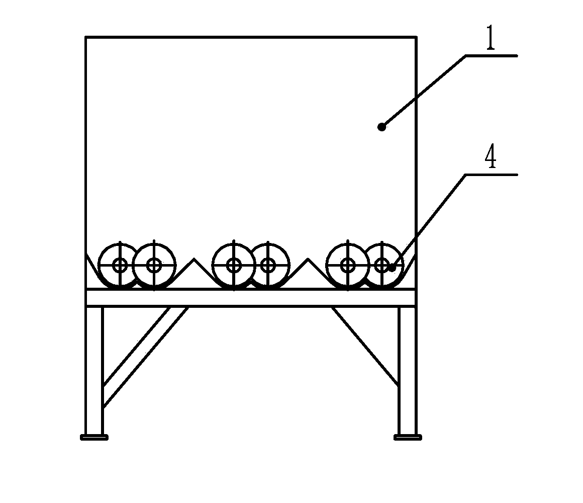
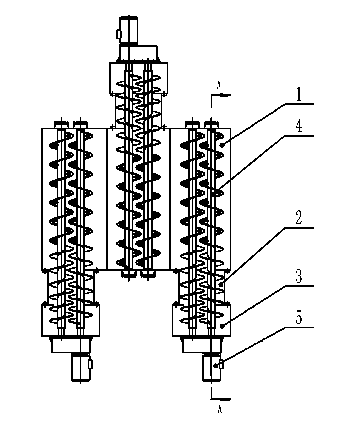
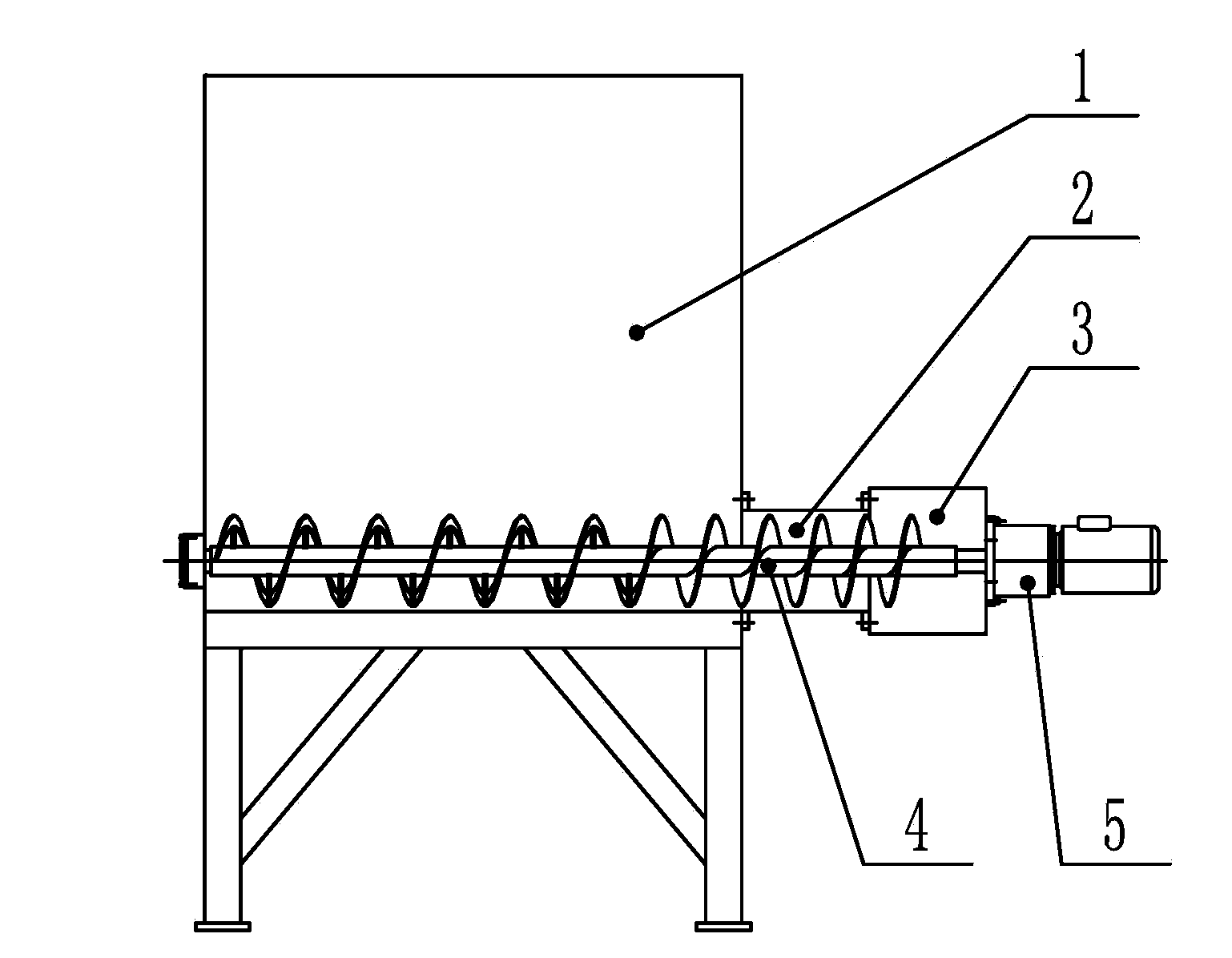
[0051] see Figure 1-3 , which shows a buffer feed bin of a preferred embodiment of the present invention. The buffer feed bin includes: a storage bin body 1; a discharge pipe body 2, which is arranged on the side wall of the storage bin body 1; a discharge hopper 3; The body 1 is connected and communicated; the discharge screw unit 4 is arranged in the storage bin body 1, the discharge pipe body 2 and the discharge hopper 3, and is used to push the material in the storage bin body to the discharge hopper 3; and The output screw unit driving mechanism 5 is connected with the output screw unit 4 to drive the output screw unit 4 to rotate.

[0052] Preferably, two or all of the storage bin body, the discharge pipe body 2 and the discharge hopper 3 are integrally structured.

[0053]Preferably, the number of the discharge pipe body 2 is two or more, each discharge pipe body 2 has two or more discharge screw units 4, each discharge pipe body 2 Each discharge screw unit 4 inside...

Embodiment 2

[0067] See you again Figure 1-3 , which shows a schematic diagram of a buffer feed bin in a preferred embodiment of the present invention. The buffer feed bin of this preferred embodiment may include: a storage bin body 1 for storing materials; a discharge screw unit (hereinafter referred to as "discharge screw") 4 for pushing materials; Spiral discharge pipe body (hereinafter specifically defined as "discharge spiral pipe") 2; discharge hopper 3 for discharge; discharge screw unit drive mechanism for driving the discharge screw rotation (hereinafter referred to as "discharge spiral pipe") 2; Discharge screw drive mechanism") 5; the discharge spiral tube 2 is located at the bottom of the storage bin body 1 and is connected to the storage bin body 1 and the discharge hopper 3 respectively, or the storage bin body 1 and the discharge spiral tube 2 and two or all of the discharge hopper 3 are integral structures; the discharge screw 4 is located in the storage bin body 1, the d...

Embodiment 3

[0084] see Figure 4-6 , which shows a schematic diagram of a buffer feeding silo in another preferred embodiment of the present invention. The buffer feed bin of this preferred embodiment includes: a storage bin body 1 for storing materials; a discharge screw 4 for pushing materials; a discharge spiral tube 2 for sealing a part of the discharge screw; as a discharge flow The discharge hopper 3 of the road; the discharge screw drive mechanism 5 for driving the discharge screw to rotate; the discharge spiral tube 2 is located at the bottom of the storage bin body 1 and is connected to the storage bin body 1 and the discharge hopper 3 respectively Connected; the discharge screw 4 is located in the storage bin body 1, the discharge spiral tube 2 and the discharge hopper 3; the power output end of the discharge screw drive mechanism 5 that drives the discharge screw is connected to the discharge The feed screw 4 is connected and can drive the discharge screw 4 to rotate.

[0085...


PUM


Abstract

A caching feeding bin comprises a storage bin body, a discharge tube body, a discharge hopper, discharge spiral units and a discharge spiral unit drive mechanism. The discharge tube body is arranged on the side wall of the storage bin body. The discharge hopper is sequentially connected and communicated with the discharge tube body and the storage bin body. The discharge spiral units are arranged in the storage bin body, the discharge tube body and the discharge hopper and used for pushing materials in the storage bin body into the discharge hopper. The output end of the discharge spiral unit drive mechanism is connected with the discharge spiral units and drives the discharge spiral units to rotate. Due to the fact that the discharge speed of the materials is related to the rotating speed of the discharge spiral units, the constant discharge speed can be adjusted by controlling the rotating speed of the discharge spiral units.

Description

technical field [0001] The invention relates to the field of material storage, in particular to a buffer feeding bin. Specifically, it relates to a buffer feeding bin capable of storing bulk or paste incoming materials and stably outputting them. Background technique [0002] Coal slime, sludge, calcium carbide mud, papermaking waste, red mud, converter dust and other high-concentration paste materials are viscous materials in the industrial production process. In order to promote the development of circular economy, make full use of precious natural resources and reduce environmental pollution. pollution, it needs to be disposed or utilized in a harmless, reduced, and resourceful manner. During the disposal or transportation of these viscous materials, a relatively constant material supply rate is often required, such as the burning of coal slime, sewage Drying of mud, drying and crushing of calcium carbide mud, etc. In addition, conveying equipment such as belt conveyors...

Claims


Application Information

Patent Timeline
Patent Type & Authority Applications(China)
IPC IPC(8): B65G65/46B65G33/18B65D88/68
Inventor 巩长勇吴淼孙浩肖高忠
Owner 光大清洁技术股份有限公司
Why Eureka
Try Eureka