
Vertical folding mechanism of drawing folding machine

A stacking machine and vertical folding technology, applied in the direction of folding thin materials, sending objects, thin material processing, etc., can solve the problems of folding edge compaction, false creases, troublesome manual operation, etc., to achieve strict consistency of folding width, Prevent jamming or wrinkling, neatly folded effect

Inactive Publication Date: 2014-03-05
NINGBO RONGHUA OFFICE EQUIP
View PDF7 Cites 3 Cited by
  • Summary
  • Abstract
  • Description
  • Claims
  • Application Information

AI Technical Summary

Problems solved by technology

[0005] Combining the above text with the accompanying drawings of the patent document, it can be seen that: (1) Before the drawing is ready to be folded, the drawing only uses the inner side of the right end plate and the rear side of the worktable as a positioning reference, and then only Placed on the workbench without specific positioning means, the drawings are prone to displacement, which affects the subsequent folding process; (2) The drawings are pressed down by the front and rear pressing boards to realize the folding of the drawings again and again. However, the front and rear press boards are hinged structures, which makes it impossible for the press ends of the front and rear press boards to completely compact the folded edges, so that the pressed creases are not real; The reciprocating movement of the rod completes the folding of the drawing. Manual operation is not only cumbersome and costly, but also the trajectory and distance of the manual operation cannot be completely consistent, which leads to the situation that the folding width is different and affects the folding quality.

Method used


Image

  • Vertical folding mechanism of drawing folding machine

Examples


Embodiment Construction

[0021] The present invention will be further specifically described below in conjunction with embodiments, but it is not limited thereto.

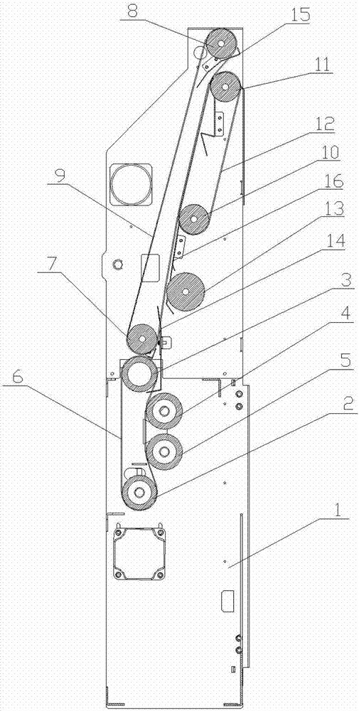
[0022] Such as figure 1 As shown, the vertical folding mechanism of the folding machine of the present invention includes a base 1, an active roller 2, a passive roller 3, an upper auxiliary roller 4, a lower auxiliary roller 5, a belt 6, a first driving axle 7, a first driven axle 8, The long conveyor belt 9, the second driving axle 10, the second driven axle 11, the short conveyor belt 12, the paper feeding secondary shaft 13, the lead-in plate 14, the lead-out plate 15, and the conveying plate 16.

[0023] The active roller 2 and the passive roller 3, the upper secondary roller 4 and the lower secondary roller 5 are respectively arranged symmetrically with respect to the same straight line. The belts 6 are arranged in parallel and tightly fitted to the active roller 2 and the passive roller 3. On the periphery, one side of the upper seconda...


PUM


Abstract

The invention provides a vertical folding mechanism of a drawing folding machine. The vertical folding mechanism comprises a base (1), a driving rolling barrel (2), a driven rolling barrel (3), an upper subshaft (4), a lower subshaft (5) and belts (6). The driving rolling barrel (2) and the driven rolling barrel (3) are symmetrically arranged relative to a straight line, the upper subshaft (4) and the lower subshaft (5) are symmetrically arranged relative to the same straight line, the multiple belts (6) are arranged in parallel and are closely arranged to the periphery of the driving rolling barrel (2) and the periphery of the driven rolling barrel (3) in a matched mode, one side of the upper subshaft (4) and one side of the lower subshaft (5) are pressed on the belts (6), the driving rolling barrel (2) is driven by a servo motor, and the axis distance of the upper subshaft (4) and the lower subshaft is smaller than that of the driving rolling barrel (2) and the driven rolling barrel (3). When the vertical folding mechanism of the drawing folding machine is used for folding drawings, the operation is simple, human cost is low, locating is good, folds are clear and linear, and folding widths are consistent.

Description

technical field [0001] The invention relates to a folding device suitable for drawings used in machinery, engineering, construction and other industries, in particular to a vertical folding mechanism of a folding machine. Background technique [0002] A stacking machine is a machine that specializes in folding printed and copied large-format drawings into specifications for archiving. The folding machine of the prior art generally includes a horizontal folding mechanism and a vertical folding mechanism. The horizontal folding mechanism folds the large-format drawings horizontally into the width of the archive specification, such as a width of 210mm when folded into A4 specifications, and the vertical folding mechanism vertically folds the large-format drawings. It is folded into the length of the archive standard, such as the length of 297mm folded into the A4 standard. [0003] The Chinese utility model patent with the notification number CN201087052Y discloses a stacking...

Claims


Application Information

Patent Timeline
Patent Type & Authority Applications(China)
IPC IPC(8): B65H45/16B65H37/06
Inventor 杜建国施国昌朱荣华王丹峰王站
Owner NINGBO RONGHUA OFFICE EQUIP
Learn More