Eureka AIR delivers breakthrough ideas for toughest innovation challenges, trusted by R&D personnel around the world.

Sleeve magnetism-gathering magnetic circuit structure used for permanent magnetism eddy transmission apparatus

A transmission device, permanent magnet eddy current technology, applied in the direction of electromechanical transmission device, electromechanical device, electric components, etc., can solve the problems of frequent decoupling, demagnetization, permanent magnet damage, etc., to achieve less eddy current loss, less permanent magnet material, manufacturing low cost effect

Active Publication Date: 2014-03-05
LIAOYANG TAIKE LEINUO SCI & TECH
View PDF5 Cites 4 Cited by
  • Summary
  • Abstract
  • Description
  • Claims
  • Application Information

AI Technical Summary

Problems solved by technology

When the early permanent magnet synchronous seal drive technology was applied to equipment such as magnetic pumps and magnetic drive agitators, it often encountered unfavorable conditions such as frequent decoupling due to high temperature, corrosion or overload, which may lead to The permanent magnet on the rotor is damaged, demagnetized and other problems

Method used


Image

  • Sleeve magnetism-gathering magnetic circuit structure used for permanent magnetism eddy transmission apparatus
  • Sleeve magnetism-gathering magnetic circuit structure used for permanent magnetism eddy transmission apparatus
  • Sleeve magnetism-gathering magnetic circuit structure used for permanent magnetism eddy transmission apparatus

Examples


Embodiment 1

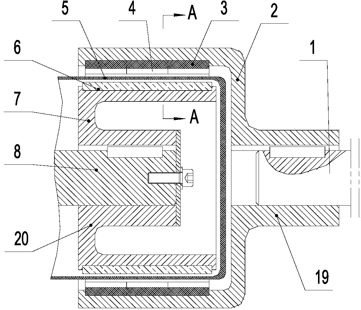
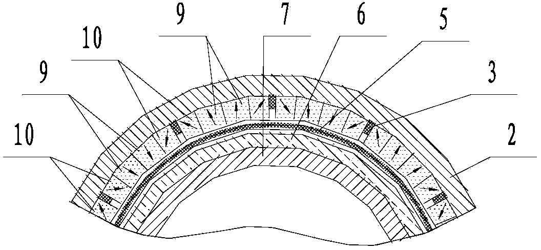
[0027] Such as figure 1 , figure 2 As shown, a sleeve-type magnet-concentrating magnetic circuit structure for a permanent magnet eddy current transmission device includes a permanent magnet rotor as the first outer rotor 19 and an eddy current ring rotor as the first inner rotor 20. The permanent magnet rotor consists of The cylindrical first outer rotor body 2 is composed of twelve sets of first permanent magnet groups 4, and the first permanent magnet groups 4 are bonded and fixed on the inner surface of the first outer rotor body 2 by magnetically conductive glue; the eddy current ring The rotor is composed of a cylindrical first inner rotor body 7 and a vortex ring 6. The vortex ring 6 is a circular structure made of copper material. The vortex ring 6 is arranged on the side wall of the first inner rotor body 7 through thermal expansion connection. On the outer surface, the first permanent magnet group 4 corresponds to the eddy current ring 6, and there is a gap between...

Embodiment 2

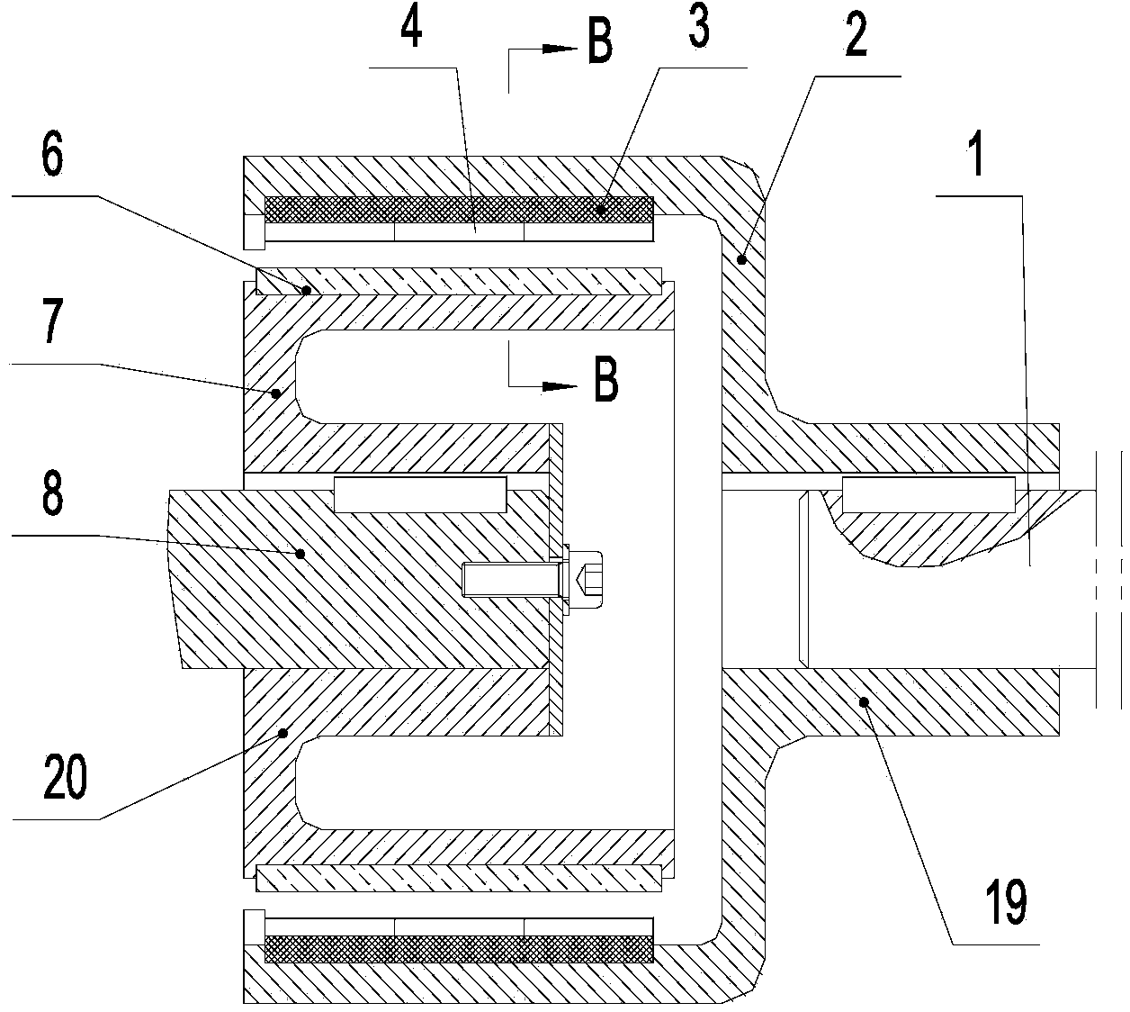
[0032] Such as image 3 , Figure 4 As shown, a sleeve-type magnet-concentrating magnetic circuit structure for a permanent magnet eddy current transmission device includes a permanent magnet rotor as the first outer rotor 19 and an eddy current ring rotor as the first inner rotor 20. The permanent magnet rotor consists of The cylindrical first outer rotor body 2 is composed of eighteen sets of first permanent magnet groups 4, and the first permanent magnet groups 4 are bonded and fixed on the inner surface of the first outer rotor body 2 by magnetically conductive glue; the eddy current ring The rotor is composed of a cylindrical first inner rotor body 7 and a vortex ring 6. The vortex ring 6 is a circular structure made of copper material. The vortex ring 6 is arranged on the side wall of the first inner rotor body 7 through thermal expansion connection. On the outer surface, the first permanent magnet group 4 corresponds to the eddy current ring 6, and there is a gap betwe...

Embodiment 3

[0037] Such as Figure 5 , Image 6 As shown, a sleeve-type magnet-concentrating magnetic circuit structure for a permanent magnet eddy current transmission device includes an eddy current ring rotor as the second outer rotor 21 and a permanent magnet rotor as the second inner rotor 22. The eddy current ring rotor consists of The cylindrical second outer rotor body 14 is composed of a vortex ring 6, the vortex ring 6 is an annular structure made of copper material, and the vortex ring 6 is fixed on the inner surface of the cylinder wall of the second outer rotor body 14 by screws; The permanent magnet rotor is composed of a cylindrical second inner rotor body 16 and twelve sets of second permanent magnet groups 15, and the second permanent magnet groups 15 are bonded and fixed on the outer surface of the side wall of the second inner rotor body 16 by magnetically conductive glue. The second permanent magnet group 15 is corresponding to the eddy current ring 6, and there is a ...


PUM


Abstract

The invention provides a sleeve magnetism-gathering magnetic circuit structure used for a permanent magnetism eddy transmission apparatus, and belongs to the field of permanent magnetism transmission technologies. Compared with a sleeve permanent magnetism eddy transmission apparatus adopting a discrete magnetic circuit structure, a torque or the transmission power generated by permanent magnetism material per unit mass are bigger according to a sleeve permanent magnetism eddy transmission apparatus adopting the magnetic circuit structure provided by the invention. The magnetic circuit structure includes a permanent magnet rotor used as a first outer rotor and a vortex ring rotor used as a first inner rotor, each first permanent magnet set is composed of 2 to 5 magnets which tightly contact together, directions of the magnetizing magnetic polarities of magnets in the same first permanent magnet set are same, and directions of the magnetizing magnetic polarities of magnets of adjacent first permanent magnet sets are different. The magnetic circuit structure includes a vortex ring rotor used as a second outer rotor and a permanent magnet rotor used as a second inner rotor, each second permanent magnet set is composed of 2 to 5 magnets which tightly contact together, directions of magnetizing magnetic polarities of adjacent magnets in the same second permanent magnet set are same, and directions of the magnetizing magnetic polarities of adjacent second permanent magnet sets are different.

Description

technical field [0001] The invention belongs to the technical field of permanent magnet transmission, and in particular relates to a sleeve-type magnetism-concentrating magnetic circuit structure for a permanent magnet eddy current transmission device. Background technique [0002] Permanent magnet eddy current transmission technology originated from the improvement and development of permanent magnet synchronous transmission technology. When the early permanent magnet synchronous seal drive technology was applied to equipment such as magnetic pumps and magnetic drive agitators, it often encountered unfavorable conditions such as frequent decoupling due to high temperature, corrosion or overload, which may lead to The permanent magnet on the rotor is destroyed, demagnetized and other problems. In order to solve this kind of problem, the eddy current ring technology came into being. Its basic structure is to remove the permanent magnet on the driven rotor and replace it with...

Claims


Application Information

Patent Timeline
Patent Type & Authority Applications(China)
IPC IPC(8): H02K51/00
Inventor 王德喜张世伟赵克中
Owner LIAOYANG TAIKE LEINUO SCI & TECH
Why Eureka
Eureka Blog
Learn More