Constant-pressure vortex pump

A technology of vortex pumps and pump bodies, which is applied in the field of vortex pumps and water pumps, and can solve problems such as head drop, low hydraulic efficiency, and high operating noise, and achieve the effects of increasing liquid kinetic energy, improving operating efficiency, and reducing eddy current losses

Inactive Publication Date: 2019-07-23
江苏振华海科装备科技股份有限公司
View PDF0 Cites 2 Cited by
  • Summary
  • Abstract
  • Description
  • Claims
  • Application Information

AI Technical Summary

Problems solved by technology

However, the hydraulic efficiency of the centrifugal water pump with the open impeller in the prior art is relatively low, the operating noise is high, and the performance curve is hump-shaped. Once the output flow of the centrifugal water pump exceeds the rated flow, its head drops sharply

Method used


Image

  • Constant-pressure vortex pump
  • Constant-pressure vortex pump
  • Constant-pressure vortex pump

Examples


Embodiment Construction

[0017] The present invention will be further described below according to the accompanying drawings and in conjunction with the embodiments.

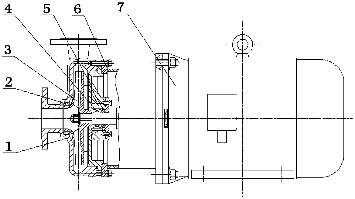
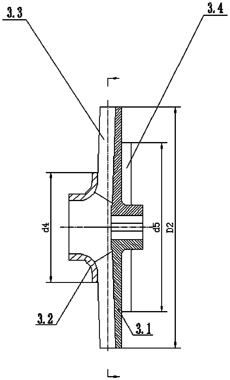
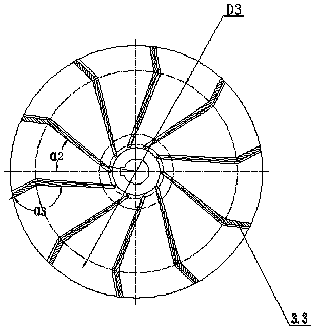
[0018] figure 1 The shown constant pressure vortex pump includes a pump body 1 , a seal ring 2 , an impeller 3 , a mechanical seal 4 , a pump cover 5 , a bracket 6 and a motor 7 . The suction end of the pump body 1 is provided with a seal ring 3 matching with the inlet of the impeller 3, and the pump cover 5 with the built-in mechanical seal 4 is coaxially sealed with the pump body 1, and the pump cover 5 is connected with the motor 7 through the bracket 6 as a whole. The output shaft end of the motor 7 axially passes through the mechanical seal 4 , and the protruding shaft end is used for installing the impeller 3 . The impeller 3 is as figure 2 , image 3 and Figure 4 As shown, it is a disc-shaped member with a diameter of D2 and a semi-open structure. The impeller 3 in this embodiment is mainly composed of 10 main blades 3.3 un...


PUM


Abstract

The invention discloses a constant-pressure vortex pump. The constant-pressure vortex pump comprises a pump body, a sealing ring, an impeller, a mechanical seal, a pump cover, a bracket and a motor. The impeller is a semi-open type structural part with the diameter D2, 8-12 main blades evenly distributed on the front face of a rear cover plate and 8-12 auxiliary blades evenly distributed on the reverse side of the rear cover plate serve as a body, and in addition, layers of front cover plates are additionally arranged at the positions of inlets of all the main blades. The suction inlet ends ofthe front cover plates are in clearance fit with the sealing ring, the external diameters d4 of the front cover plates are equal to K1D2, and K1 ranges from 0.3 to 0.4. The main blades are obliquelyarranged relative to the axis in the same direction and anticlockwise folded at the positions of the diameters D3 by one bend uniformly, the auxiliary blades are half straight strip blocks, and all the auxiliary blades are evenly distributed in the d5 circumference and radially arranged. The front cover plates have the effects of improving and stabilizing the suction capacity of the inlets of themain blades and reducing internal leakage in the structure, thus, energy losses and noise in the constant-pressure vortex pump are reduced, the hydraulic efficiency of the pump can be improved, and meanwhile generation of camel curves under the small-flow working condition is avoided.

Description

technical field [0001] The invention belongs to a technical solution in the technical field of hydraulic machinery. Specifically, the invention relates to a water pump, especially a vortex pump output according to a rated lift. Background technique [0002] Large and medium-sized ships are a kind of floating carrier with complete functions. Like industrial and civil buildings, they have safety problems and need to be equipped with corresponding fire-fighting devices. The main engine of the fire-fighting device is a centrifugal water pump, and the centrifugal water pump supporting the commercially-available fire-fighting device usually uses a constant-pressure tangential pump. The working performance of the centrifugal water pump used for fire protection is different from that of conventional centrifugal water pumps. The main difference is the output under constant pressure, that is, the output at constant head. In the centrifugal water pump structure, the component that det...

Claims


Application Information

Patent Timeline
Patent Type & Authority Applications(China)
IPC IPC(8): F04D13/06F04D29/24F04D29/42
CPCF04D13/06F04D29/242F04D29/426
Inventor 陈金平王辉肖亚东杨慧马骏孙涛
Owner 江苏振华海科装备科技股份有限公司
Why Eureka
Try Eureka