Time-frequency transform based method for identifying parameters of synchronous generator

A technology of synchronous generator and time-frequency conversion, which is applied in the control of generator, motor generator control, electronic commutation motor control, etc. It can solve the problems of large error of q-axis parameters, low precision, difficulty in resistance and reactance, etc.

Active Publication Date: 2014-03-05
STATE GRID CORP OF CHINA +2
View PDF4 Cites 29 Cited by
  • Summary
  • Abstract
  • Description
  • Claims
  • Application Information

AI Technical Summary

Problems solved by technology

The advantage of the load dump method is that it is easy to implement and the calculation method is relatively simple, but it cannot take into account the influence of the excitation voltage on the transient process, so it is not suitable for mainstream self-shunt excitation units
The effective time-domain identification method, such as the load dump method and weighted least squares algorithm, is expected to solve the influence of the excitation voltage. However, accurate power angle information is required during the q-axis load dump, and the operating conditions are difficult to adjust. Previous studies have shown that the measured d The parameters of the axis are more accurate, while the parameters of the q axis have a larger error
Numerical calculation methods mainly include magnetic circuit permeance method and finite element method, the former requires a large number of equivalents, and the accuracy is not high
The calculation amount of the finite element method is very large, and the resistance and reactance at the end and slot wedge are difficult, and the calculation accuracy needs to be further improved

Method used


Image

  • Time-frequency transform based method for identifying parameters of synchronous generator
  • Time-frequency transform based method for identifying parameters of synchronous generator
  • Time-frequency transform based method for identifying parameters of synchronous generator

Examples


Embodiment Construction

[0062] Specific embodiments of the present invention will be further described in detail below.

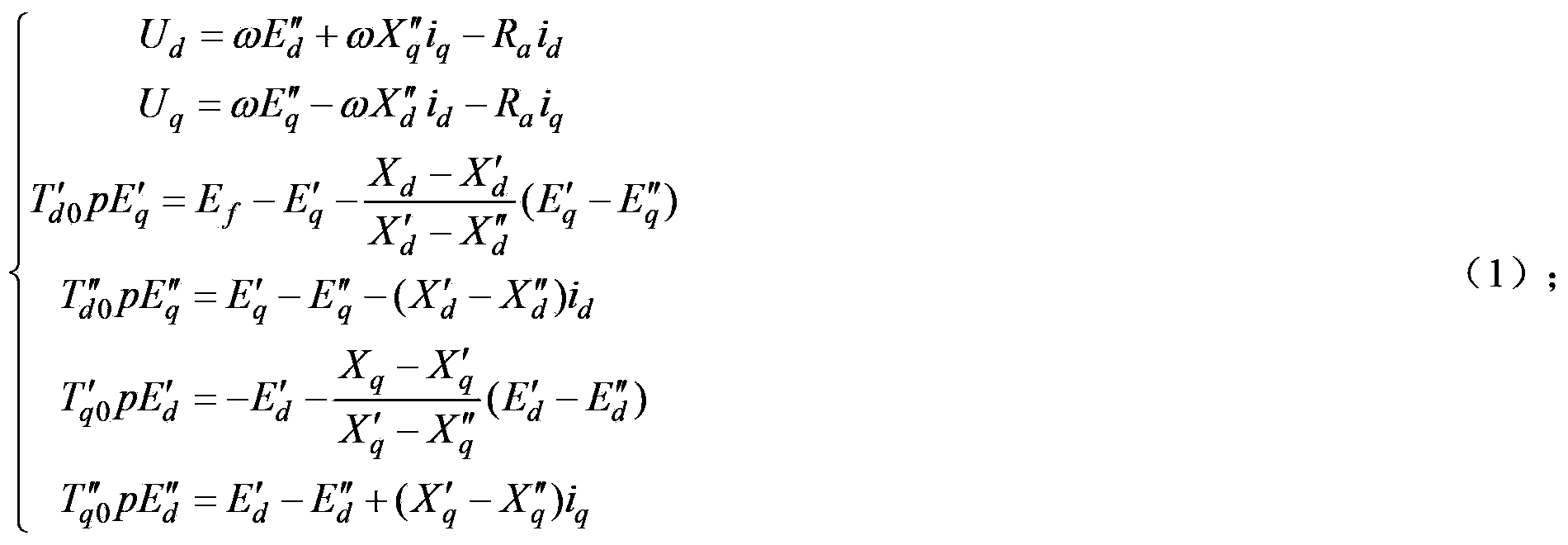
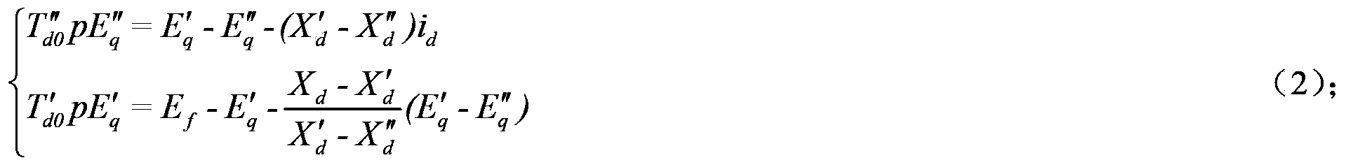
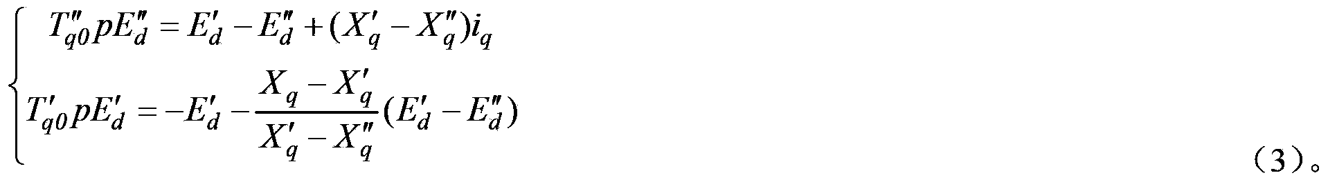
[0063] The present invention provides a synchronous generator parameter identification method based on time-frequency transformation, including:

[0064] Step S1, Laplace transform the d and q axis differential equations of the generator in the time domain in the generator model to obtain the d and q axis equations of the generator in the frequency domain, and then obtain the d and q axis integrals of the generator in the time domain through inverse Laplace transform equation.

[0065] Step S2, according to the relational expression between generator stator d, q axis voltage and state variables in the generator model, replace the state variables in the generator d, q axis integral equation in the time domain.

[0066] Step S3, assuming that the generator stator d, q axis voltage and current are column vectors composed of measured sampling points, discretizing the generator d, q a...


PUM


Abstract

The invention provides a time-frequency transform based method for identifying parameters of a synchronous generator. The method includes steps of S1. carrying out Laplace transform on a differential equation of a d axle and a q axle of a generator in time domain in a generator model to obtain an equation of the d axle and the q axle of the generator in frequency domain, and carrying out inverse Laplace transform to obtain an integral equation of the d axle and the q axle of the generator in the time domain; S. replacing state variable of the integral equation of the d axle and the q axle of the generator in the time domain; S3. dispersing the integral equation of the d axle and the q axle of the generator in the time domain into that measurable column vectors or integration of the measurable column vectors are equal to a matrix multiplying by column vectors of coefficients of the integration equation, and solving to obtain the column vectors of the coefficients of the integration equation; and S4. solving to obtain parameters of the generator model according to the relation between the column vectors of the coefficients of the integration equation and parameters of the generator. A differential equation of a generator is converted to an integration equation according to the time-frequency transform based method for identifying the parameters of the synchronous generator, stability of calculating a value is facilitated, and the problem of an unstable identification result is solved.

Description

technical field [0001] The invention relates to the technical field of power system analysis, in particular to a method for identifying parameters of a synchronous generator based on time-frequency transformation. Background technique [0002] The accuracy of the model and parameters of the synchronous generator is related to the safe and stable operation of the power grid. At present, the generator parameters used in the analysis and simulation of the power system are the theoretical values ​​or design values ​​provided by the manufacturer, or the model has to be used, because it cannot take into account Due to the influence of actual operating conditions such as eddy current, hysteresis, and saturation, the results obtained are often inconsistent with the actual operating conditions, which seriously affects the accuracy and reliability of system analysis and calculation. Therefore, the identification of generator parameters is the core of intelligent dispatching technology....

Claims


Application Information

Patent Timeline
Patent Type & Authority Applications(China)
IPC IPC(8): H02P21/14
Inventor 李志强
Owner STATE GRID CORP OF CHINA
Why Eureka
Try Eureka