Heat tube cooling system and power equipment

A heat dissipation system and power equipment technology, applied in lighting and heating equipment, indirect heat exchangers, cooling/ventilation/heating transformation, etc., can solve the problems of inconvenient maintenance of heat pipe radiators, achieve space saving and broad application prospects

Active Publication Date: 2014-03-05
HUAWEI DIGITAL POWER TECH CO LTD
View PDF3 Cites 4 Cited by
  • Summary
  • Abstract
  • Description
  • Claims
  • Application Information

AI Technical Summary

Problems solved by technology

[0006] In order to solve the problem of inconvenient maintenance of heat pipe radiators in the prior art, embodiments of the present invention provide a heat pipe cooling system and power equipment

Method used


Image

  • Heat tube cooling system and power equipment
  • Heat tube cooling system and power equipment
  • Heat tube cooling system and power equipment

Examples


Embodiment 1

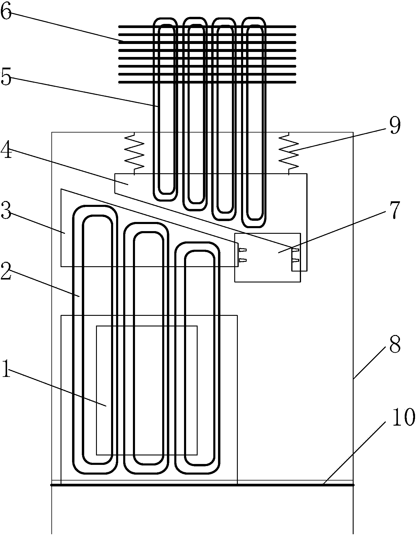
[0032] Such as figure 1 As shown, in the first aspect, the embodiment of the present invention provides a heat pipe heat dissipation system for dissipating heat from a heat generating device 1. The heat pipe heat dissipation system includes: a first heat exchange tube 2, a first heat exchange plate 3, a first The second heat exchange plate 4, the second heat exchange tube 5 and the condensing device 6, the first heat exchange tube 2 and the second heat exchange tube 5 both include an evaporation end and a condensation end, the evaporation end of the first heat exchange tube 2 is connected to the The heating device 1 contacts, the condensation end of the first heat exchange tube 2 contacts the first heat exchange plate 3, the evaporation end of the second heat exchange tube 5 contacts the second heat exchange plate 4, and the condensation end of the second heat exchange tube 5 Contact with the condensation device 6;

[0033] Such as figure 2As shown, when the heat pipe cooli...

Embodiment 2

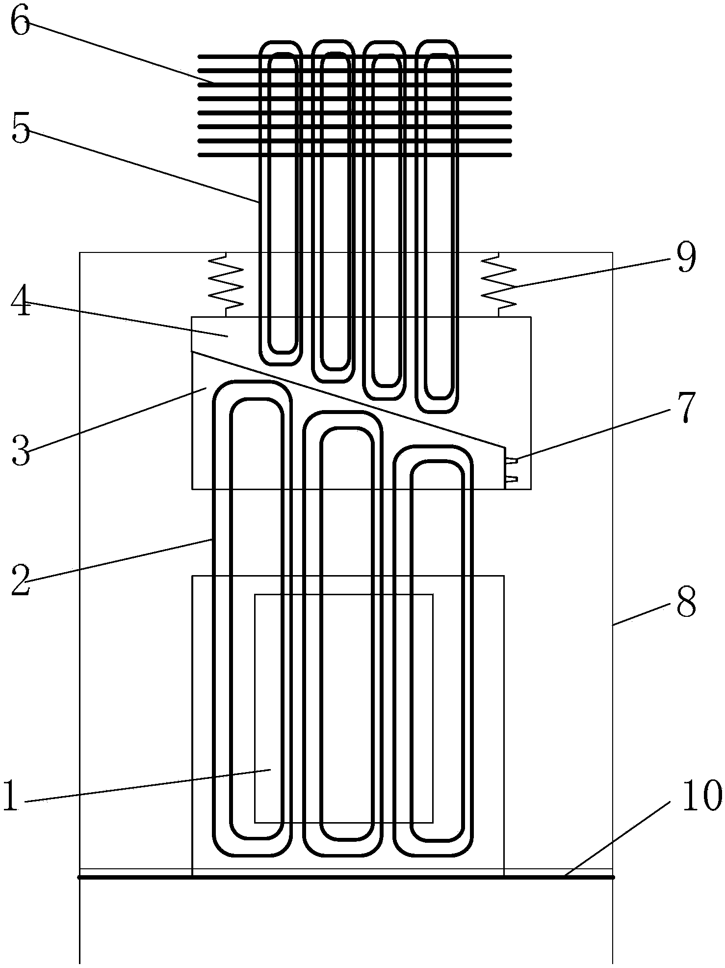
[0043] Such as figure 2 As shown, in the second aspect, the embodiment of the present invention provides a kind of power equipment, the power equipment includes: a heat pipe cooling system, a cabinet 8 and electronic components, the electronic components are arranged inside the cabinet 8, the The heat pipe cooling system is in contact with the electronic components, and the heat pipe cooling system is used for cooling the electronic components.

[0044] The structure and function of the heat pipe cooling system of the present invention is the same as that of the heat pipe cooling system in the above embodiments, and will not be repeated here. Meanwhile, the electronic components in the embodiments of the present invention are the heating device 1 in the above embodiments. When the heat dissipation system is applied in different fields, the heat generating device 1 can be different. The power equipment provided by the present invention can install the electronic components in...

Embodiment 3

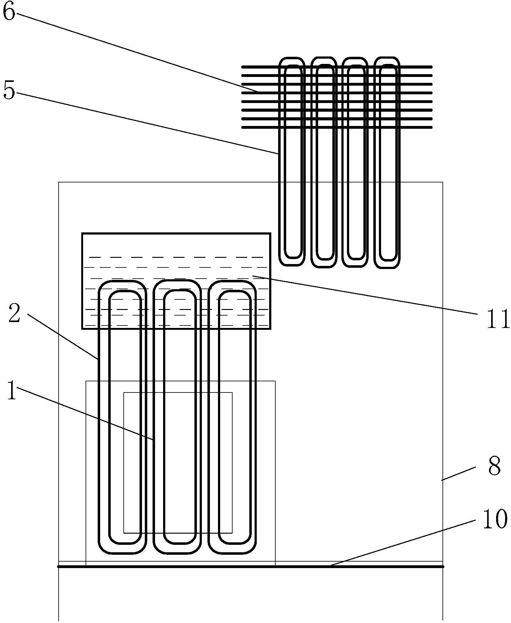
[0052] Such as image 3 As shown, in the third aspect, the embodiment of the present invention provides a heat pipe heat dissipation system for dissipating heat from the heat generating device 1, the heat pipe heat dissipation system includes: a first heat exchange tube 2, a heat exchange device with a cavity 11 the second heat exchange tube 5 and the condensation device 6, and the heat exchange medium is stored in the cavity of the heat exchange device 11, the first heat exchange tube 2 and the second heat exchange tube 5 both include an evaporation end and a condensation end, The evaporation end of the first heat exchange tube 2 is in contact with the heating device 1 , the condensation end of the first heat exchange tube 2 extends into the heat exchange medium, and the condensation end of the second heat exchange tube 5 is in contact with the condensation device 6 ;

[0053] Such as Figure 4As shown, when the heat pipe cooling system is working, the evaporation end of the...


PUM


Abstract

The invention discloses a heat tube cooling system and power equipment. The heat tube cooling system comprises first heat exchange tubes, a first heat exchange plate, a second heat exchange plate, second heat exchange tubes and a condensing unit, or the heat tube cooling system comprises the first heat exchange tubes, a heat exchange device with a cavity, the second heat exchange tubes and the condensing unit. In the working process, heat conduction between a heating device and the condensing unit can be achieved, and in the overhauling process, the heating device and the condensing unit can be separated and can be respectively maintained. The power equipment comprises the heat tube cooling system, an equipment cabinet and electronic components. By means of the heat tube cooling system and the power equipment, the heating device and the condensing unit can be mutually detached, the heating device is mounted inside the equipment cabinet, the condensing unit is mounted outside the equipment cabinet, during daily maintenance, the heating device and the condensing unit are separated, the inside of the cabinet and the outside of the cabinet can be respectively maintained, and thus the maintaining and cleaning work can be completed rapidly.

Description

technical field [0001] The invention relates to the technical field of heat dissipation, in particular to a heat pipe heat dissipation system and power equipment. Background technique [0002] With the continuous development of electronic technology, the degree of circuit integration of semiconductor devices is getting higher and higher, the power of electronic components is getting larger and the physical size is getting smaller and smaller, and the heat flux density of power electronic products is also increasing. The heat dissipation requirements of electronic products are higher. Because the loop heat pipe has the advantages of high thermal conductivity, simple structure, small size, and light weight, heat pipe radiators are mostly used in the prior art to dissipate heat from power electronic products. [0003] Heat pipe radiators in the prior art generally include an evaporator, a compensator, and a condenser connected as a whole. The above components are connected into...

Claims


Application Information

Patent Timeline
Patent Type & Authority Applications(China)
IPC IPC(8): H05K7/20F28D15/02
CPCF28D15/0275
Inventor 王超李泉明刘小虎
Owner HUAWEI DIGITAL POWER TECH CO LTD
Why Eureka
Try Eureka