Asymmetric Vertebral Bone Expander

An asymmetric, dilator technology, applied in the field of medical devices, can solve the problems of insufficient opening height, balloon puncture, and increase the medical burden of patients, and achieve the effects of low production cost, large opening force and simple structure

Active Publication Date: 2016-06-22
JIANGSU PROVINCE HOSPITAL +1
View PDF5 Cites 4 Cited by
  • Summary
  • Abstract
  • Description
  • Claims
  • Application Information

AI Technical Summary

Problems solved by technology

But the balloon type vertebral body expander that uses at present has following shortcoming: one, because the characteristic of the compressed air in the balloon, the compressed air in the balloon will expand to the position with little resistance when pressurized and expanded, and this just causes the big resistance The height of the part is not stretched enough, which leads to unsatisfactory orthopedic effect; 2. The sharp bone fragments in the vertebral body are easy to puncture the balloon, and the price of the balloon is relatively expensive, which increases the medical burden of the patient

Method used


Image

  • Asymmetric Vertebral Bone Expander
  • Asymmetric Vertebral Bone Expander

Examples


Embodiment Construction

[0010] The present invention will be further described in detail below in conjunction with the accompanying drawings and the best embodiment.

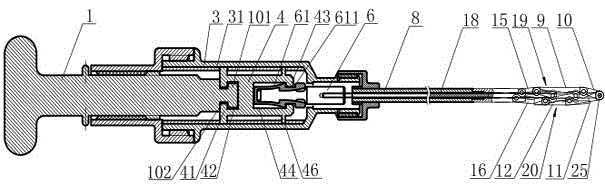
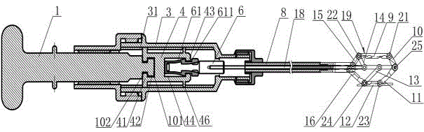
[0011] Such as figure 1 , figure 2 As shown, the asymmetric vertebral bone expander includes: a core rod 18, a core rod sleeve 8 is arranged on the core rod 18, the front end of the core rod 18 stretches out from the core rod sleeve 8, and the front end of the core rod 18 The upper and lower sides are respectively provided with an upper brace assembly 19 and a lower brace assembly 20. The upper brace assembly 19 includes: an upper front brace 10, an upper middle brace 9, an upper rear brace 15, The upper middle strut 9 , the upper front strut 10 and the upper rear strut 15 are hingedly connected by the upper front hinge shaft 21 and the upper rear hinge shaft 22 respectively, and the lower strut assembly includes: the lower front struts arranged sequentially 11. The lower middle brace 12, the lower rear brace 16, the lower middle br...


PUM


Abstract

The invention discloses an asymmetric type vertebral body expander which is large in expanding force and stable. The asymmetric type vertebral body expander comprises a core rod, wherein an upper portion supporting plate assembly and a lower portion supporting plate assembly are arranged at the front end of the core rod, and the core rod is sleeved with a core rod sleeve. The upper portion supporting plate assembly comprises an upper portion front supporting plate, an upper portion middle supporting plate and an upper portion rear supporting plate, wherein the upper portion front supporting plate, the upper portion middle supporting plate and the upper portion portion rear supporting plate are sequentially connected through an upper portion front hinge shaft and an upper portion rear hinge shaft. The lower portion supporting plate assembly comprises a lower portion front supporting plate, a lower portion middle supporting plate and a lower portion rear supporting plate, wherein the lower portion front supporting plate, the lower portion middle supporting plate and the lower portion rear supporting plate are sequentially connected through a lower portion front hinge shaft and a lower portion rear hinge shaft, the upper portion front supporting plate, the lower portion front supporting plate and the core rod are hinged to the front hinge shaft, the upper portion rear supporting plate and the lower portion rear supporting plate are hinged to the core rod sleeve, one end of an upper portion supporting rod is hinged to the upper portion rear hinge shaft, the other end of the upper portion supporting rod is hinged to the core rod, one end of a lower portion supporting rod is hinged to the lower portion rear hinge shaft, the other end of the lower portion supporting rod is hinged to the core rod, the expanding height of the upper portion supporting rod is different from the expanding height of the lower portion supporting rod, the rear end of the core rod is connected with a connecting assembly in a handle portion shell, and a handle connecting rod matched with the handle portion shell in a threaded mode is connected to the connecting assembly.

Description

technical field [0001] The invention relates to the field of medical devices, in particular to a vertebral bone expander used in vertebral body orthopedic surgery. Background technique [0002] Vertebral body diseases caused by trauma or pathological reasons, such as: vertebral body fracture, thoracic intervertebral disc degeneration, thoracic pseudarthrosis, thoracic spondylolisthesis, etc., usually require surgical orthopedic treatment. During surgery, it is necessary to use a vertebral body expander to stretch the vertebral body at the lesion, and then implant bone cement in the stretched vertebral body. And the vertebral body bone expander that uses at present is a kind of balloon bone expander, and its working principle is: the pathological vertebral body is strutted after the balloon is expanded by pressurization. But the balloon type vertebral body expander that uses at present has following shortcoming: one, due to the characteristic of the compressed air in the bal...

Claims


Application Information

Patent Timeline
Patent Type & Authority Patents(China)
IPC IPC(8): A61B17/56A61M29/00
CPCA61B2017/564A61M29/00A61B17/8858
Inventor 殷国勇张宁任永信吴剑金桃顾鑫磊余利鹏
Owner JIANGSU PROVINCE HOSPITAL
Why Eureka
Try Eureka