Blisk blade electrolytic finishing forming device and blisk blade machining forming method

An electrolytic finishing and integral blisk technology, applied in electrochemical machining equipment, metal processing equipment, manufacturing tools, etc., can solve the problem that the machining accuracy and surface quality are difficult to meet the machining requirements, the machining accuracy is not high, and the blade accuracy cannot be achieved. requirements and other issues, to meet the needs of relative motion, high processing accuracy, and high processing efficiency.

Inactive Publication Date: 2014-03-12
NANJING UNIV OF AERONAUTICS & ASTRONAUTICS +1
View PDF4 Cites 42 Cited by
  • Summary
  • Abstract
  • Description
  • Claims
  • Application Information

AI Technical Summary

Problems solved by technology

Since the shape of the blades of the overall blisk of the aero-engine is mostly a free-form surface, the electrolytic machining process used in the past is difficult to meet the processing requirements in terms of machining accuracy and surface quality, so further research on the overall blisk electrolytic machining process is required
At present, the processing of a single independent blade mainly adopts the copy-type electrolytic forming process, while the processing of the overall blisk blade mainly adopts the numerical control generating electrolytic forming pro

Method used


Image

  • Blisk blade electrolytic finishing forming device and blisk blade machining forming method
  • Blisk blade electrolytic finishing forming device and blisk blade machining forming method
  • Blisk blade electrolytic finishing forming device and blisk blade machining forming method

Examples


Embodiment 1

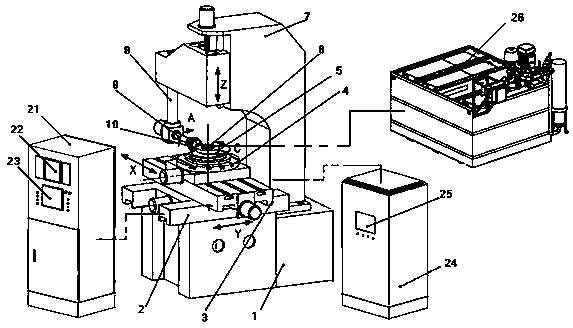
[0032] Such as Figure 1 to Figure 3 As shown, a whole blisk blade electrolytic finishing forming device includes a five-axis four-linkage electrolytic machining machine tool, a forming cathode installed on the five-axis four-linkage electrolytic machining machine tool for blade processing, and a five-axis four-linkage electrolytic machining machine tool Connected intelligent pulse power supply and control system, electrolyte delivery device connected to the forming cathode of blade processing;

[0033] The five-axis four-link ECM machine tool comprises a machine bed (1), a Y-axis slide table (2) installed on the machine bed (1), a Y-axis installed on the Y-axis slide table (2), The X-axis slide (3) installed on the upper part of the Y-axis slide (2), the X-axis installed on the X-axis slide (3), and the integral blisk (4) installed on the upper part of the X-axis slide (3) , the rotary table (5) installed on the blisk (4), the C-axis (6) installed in the rotary table (5), th...

Embodiment 2

[0041] A method for electrolytic finish machining of integral blisk blades, including determination of the path of the formed cathode entering the inter-blade passage, selection of machining feed angle and speed, and control of the machining process;

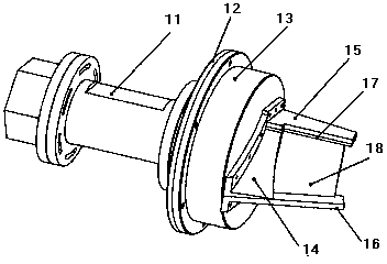
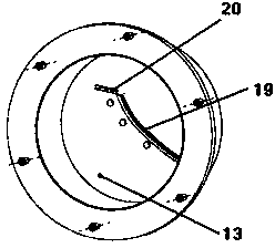
[0042] First, the electrolytic finishing forming cathode (10) is installed on the A-axis (9) of the five-axis electrolytic machining machine tool, and then the rough-machined integral impeller is installed on the C-axis (6), through the integrated industrial control computer (23 ) on the electrolytic machining control software to generate the electrolytic finishing forming cathode (10) movement path, movement angle and movement speed, and then control the X-axis, Y-axis, Z-axis and A-axis (9) on the five-axis electrolytic machining machine tool Five-axis movement with the C-axis (6), so that the cathode (10) formed by electrolytic finishing enters the channel between the blades of the overall blisk and reaches the predetermined p...


PUM


Abstract

The invention discloses a blisk blade electrolytic finishing forming device and a blisk blade machining forming method. The device comprises a five-axis four-linkage electrolytic machining machine tool, a forming cathode, an intelligent pulsed power supply, a control system and an electrolyte conveying device, the forming cathode is arranged on the five-axis four-linkage electrolytic machining machine tool and used for machining a blade, the intelligent pulsed power supply and the control system are connected with the five-axis four-linkage electrolytic machining machine tool, and the electrolyte conveying device is connected with the forming cathode for machining the blade. The electrolytic finishing forming device is reasonable in design, high in machining efficiency, especially high in machining precision, capable of achieving free-form surface blisk blade finishing well, and capable of meeting the aero-engine blisk blade machining precision requirement. The machining forming method is strong in operability, high in work efficiency, high in precision of the machined and manufactured blisk blade and capable of overcoming the defects in the prior art.

Description

technical field [0001] The invention relates to a molding device and a processing molding method for the electrolytic finishing of an integral blisk blade of an aeroengine free-form surface, and belongs to the technical field of electrolytic processing. Background technique [0002] The use of blisks in aero-engines is the development trend of aero-engine technology in the world. In order to expand the application of blisks in aero-engines, the manufacturing problems of blisks must first be solved. At present, the number of blisks used in my country's aero-engines is small, and the main reason why they cannot be widely used is that the manufacturing technology of blisks has not yet been solved. The difficulty in manufacturing the blisk of an aero-engine lies in the complex profile of the blade, high processing accuracy and surface quality requirements, extremely high blade processing consistency, blade processing deformation, and the materials used. The blade surface of the...

Claims


Application Information

Patent Timeline
IPC IPC(8): B23H9/00B23H3/00
Inventor 王福元徐家文赵建社
Owner NANJING UNIV OF AERONAUTICS & ASTRONAUTICS
Why Eureka
Try Eureka