Fixed-length Cutting Mechanism for Paper Bag Carrying Hand Rope
A cutting mechanism and paper bag technology, applied in papermaking, bagmaking operations, paper/cardboard containers, etc., can solve the problems of low production efficiency, inconvenient production management, laborious operation, etc., and achieve a good degree of automation, easy production management, and high efficiency high effect
- Summary
- Abstract
- Description
- Claims
- Application Information
AI Technical Summary
Problems solved by technology
Method used
Image
Examples
Embodiment 1
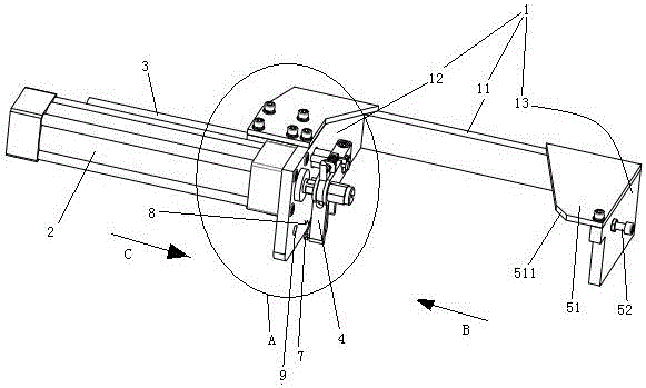
[0027] Embodiment one, see figure 1 , a portable paper bag hand rope fixed-length cutting mechanism, including a frame 1. The frame 1 includes a main body 11 extending in the left-right direction, a left end plate 12 disposed at the left end of the main body 11 , and a right end plate 13 disposed at the right end of the main body.
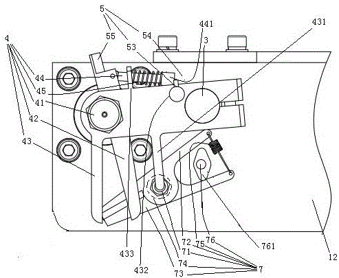
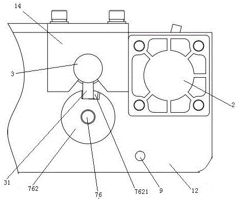
[0028]Both the left end plate 12 and the right end plate 13 are located in a vertical plane extending in the front-rear direction. The right side of the left end plate 12 is provided with a cutter 7 . A feeding spring 8 is arranged between the cutter 7 and the left end plate 12 . The left end plate 12 is provided with a hand rope positioning hole 9 passing through the left end plate along the left and right directions. The left side of the left end plate 12 is fixedly connected with a cylinder 2 and a drive rod 3 is pierced therethrough. The air cylinder 2 and the drive rod 3 extend in parallel and in the left-right direction. The piston rod o...
Embodiment 2
[0038] Embodiment two, see Figure 6 , the difference from the first embodiment is that an opening block 51 matching with the first opening guide surface 511 is provided on the first clip 42 .
[0039] see Figure 7 , the middle part of the cutter folding rod 76 is hinged on the left end plate 12 to form a lever structure, and the left end of the cutter folding rod 76 is provided with an inclined lead-in rod 763 . When the driving rod 3 moved to the right, the driving block 31 slid along the lead-in rod 763 so that the right end of the cutter closing bar 76 was raised up, and the result of driving the right end of the closing bar 76 was raised so that the front end of the chopping block 72 and the blade 73 were closed and the rear end opened. Open and complete the cutting action.
Embodiment 3
[0040] Embodiment three, see Figure 8 The difference from the first embodiment is that the protruding head 441 doubles as the opening block 51 at the same time. An inclined surface 531 is provided on the locking block 53 in the open state, and the inclined surface 531 constitutes an opening guide surface for opening the chuck. The opening block is no longer provided on the right end plate.
PUM
 Abstract
Description
Claims
Application Information
 - R&D
- Intellectual Property
- Life Sciences
- Materials
- Tech Scout
- Unparalleled Data Quality
- Higher Quality Content
- 60% Fewer Hallucinations
Browse by: Latest US Patents, China's latest patents, Technical Efficacy Thesaurus, Application Domain, Technology Topic, Popular Technical Reports.
© 2025 PatSnap. All rights reserved.Legal|Privacy policy|Modern Slavery Act Transparency Statement|Sitemap|About US| Contact US: help@patsnap.com


