Aerodynamic heating furnace

An aerodynamic and heating furnace technology, which is applied in the direction of heating devices and other non-combustion heat generation, can solve the problems of single application method, low heating efficiency, and no involvement of small heating devices, and achieve simple maintenance, high heating efficiency, Effect of heating method safety

Inactive Publication Date: 2014-03-12
XIAN AEROSPACE CHEM PROPULTION PLANT
View PDF6 Cites 12 Cited by
  • Summary
  • Abstract
  • Description
  • Claims
  • Application Information

AI Technical Summary

Problems solved by technology

[0002] At present, the heating equipment used by most enterprises and households in our country mostly adopts the heating methods of combustion heating, electric heating tube heating and microwave heating, which have low heating efficiency and single application method. The patents related to this heating method mainly include: aerodynamic heating furnace And the method of generating heat energy (patent number 200910021648.6), the rapid cooling device of air-powered furnace (patent number 201020689393.9), the related articles mainly introduce the advantages of this heating method around these two patents
The above content is mainly for the introduction of large-scale industrial equipment, but not for small-scale heating devices

Method used


Image

  • Aerodynamic heating furnace
  • Aerodynamic heating furnace
  • Aerodynamic heating furnace

Examples


Embodiment Construction

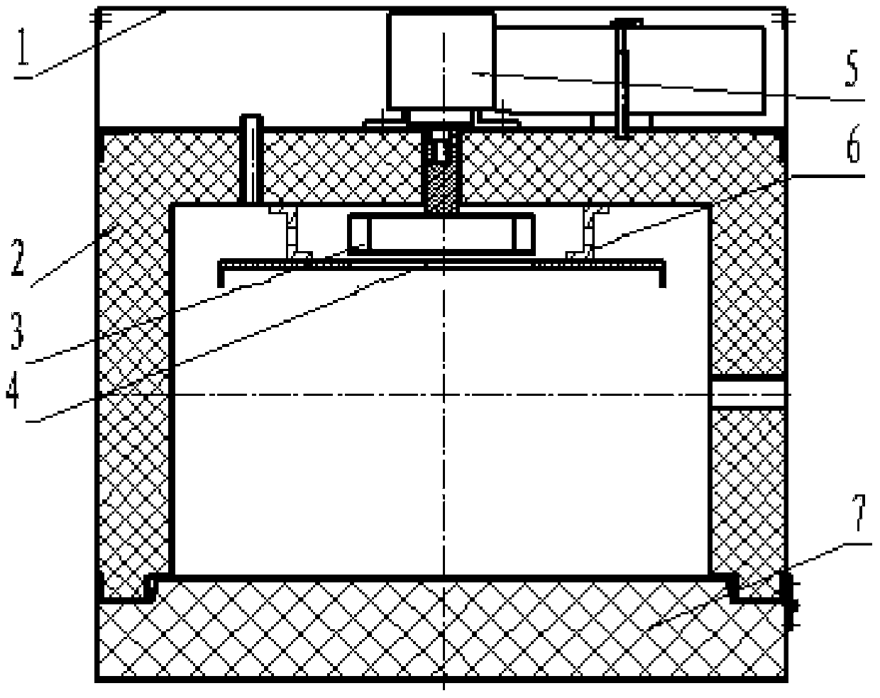
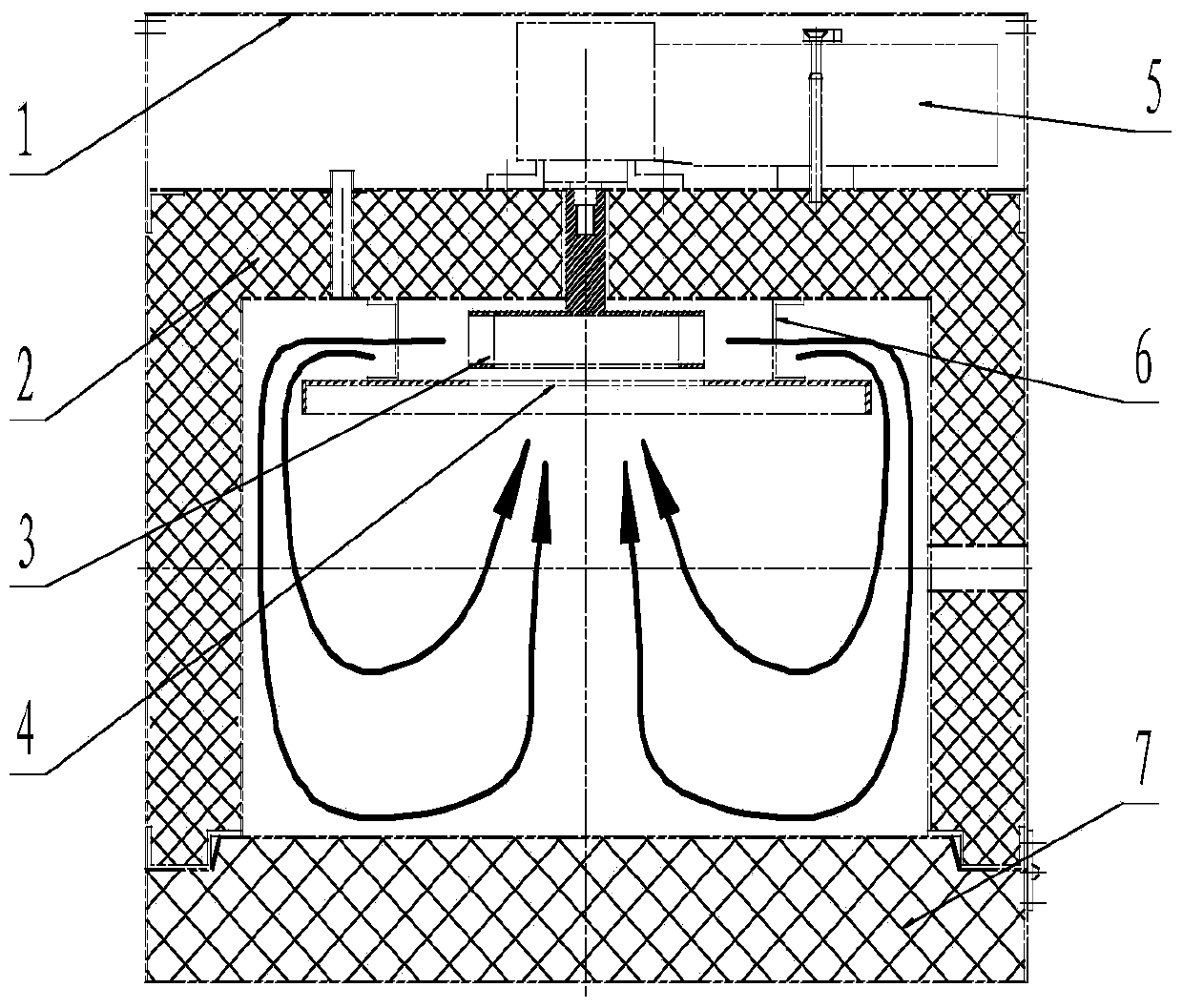
[0028] Such as figure 1 As shown, the present embodiment includes a rear protective plate 1, a furnace body 2, an impeller 3, a deflector 4, a motor 5, a deflector support 6, and a furnace door 7. The back cover 1 is for concealing the motor 5 to ensure the overall appearance is beautiful, and is a plate structure; the furnace body 2 is a square structure, and the motor 5 adopts a shaft-end air-cooled motor. The impeller 3 adopts a centrifugal impeller.

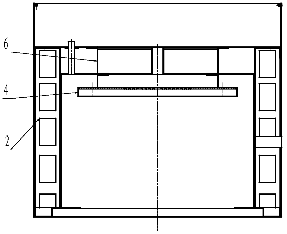
[0029] The body of furnace 2 is a frame structure. There is a mounting hole for the impeller shaft in the middle part of the rear wall plate of the body of heater 2 . The motor 5 is fixed on the outer surface of the rear wall of the furnace body 2; the output shaft of the motor 5 is connected with the impeller shaft. The impeller 3 is located in the furnace body 2 . The deflector 4 is installed in the body of heater by the deflector bracket 6, and is fixed on the inner surface of the rear wall of the body of heater 2. Th...


PUM


Abstract

The invention provides an aerodynamic heating furnace. An impeller is located in a furnace body. A guide plate is installed in the furnace body through a guide plate support and is fixed to the inner surface of a rear wall plate of the furnace body. Two surfaces, adjacent to the impeller, of the guide plate are spaced. An air inlet hole is formed in the center of the guide plate, and the air inlet hole and the center of the impeller are concentric. A plurality of airflow holes are evenly distributed in the circumference of an annular impeller support. The sum of the sectional areas of the airflow holes is 1-2 times the circumference area of the impeller. A guide edge protruding in the axial direction is arranged on the outer circumference of the guide plate and the guide edge faces towards an inner wall of the furnace body. Turbulence is increased by the right-angled guide edge and heating uniformity and the heating depth are improved by the right-angle guide edge. According to the aerodynamic heating furnace, wind energy is used as a heating medium, the impeller is driven by a motor, so that the wind energy is converted into thermal energy, high-uniformity of a temperature field is achieved through flowing of the wind energy, heating elements such as a heating tube can be omitted, the number of parts used for keeping the uniformity of the temperature field is reduced, the number of partial high temperature points is reduced, the furnace body heat capacity is reduced, the number of furnace body heat bridges is reduced, and therefore the purposes that energy consumption is reduced and the energy-saving effect is achieved are achieved.

Description

technical field [0001] The invention relates to a heating device, in particular to a heating device which changes the air flow state as a heating source. Background technique [0002] At present, the heating equipment used by most enterprises and households in our country mostly adopts the heating methods of combustion heating, electric heating tube heating and microwave heating, which have low heating efficiency and single application method. The patents related to this heating method mainly include: aerodynamic heating furnace And the method of generating heat energy (patent number 200910021648.6), the rapid cooling device of air-powered furnace (patent number 201020689393.9), the related articles mainly introduce the advantages of this heating method around these two patents. The above content is mainly for the introduction of large industrial equipment, but not for small heating devices. At the same time, the society's requirements for heating quality, safety, environme...

Claims


Application Information

Patent Timeline
Patent Type & Authority Applications(China)
IPC IPC(8): F24J3/00
Inventor 王照波李文岛野延年朱传俊
Owner XIAN AEROSPACE CHEM PROPULTION PLANT
Why Eureka
Try Eureka